
Timelapses are not only neat to watch but they can be a great way to show the passage of time in your project - from a bustling crowd of people to an approaching storm to a plant sprouting - we’re able to show things happening that we wouldn’t be able to see with the naked eye - and we can make our timelapses even more cinematic by adding in some motion. Things like hyperlapses can give us perspective change, movement, and depth. On a small scale we do this with a motorized slider - these normally retail anywhere from $400 on up into the thousands of dollars, but we’re going to make our own for around $250. Like all my DIY projects this isn’t the cheapest motorized slider you can build - but, for the price this is a great piece of gear that can really add some production value to your timelapses.
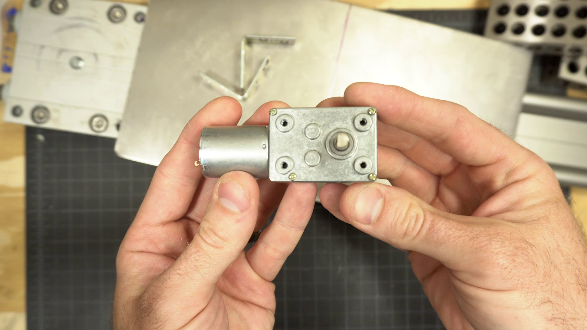
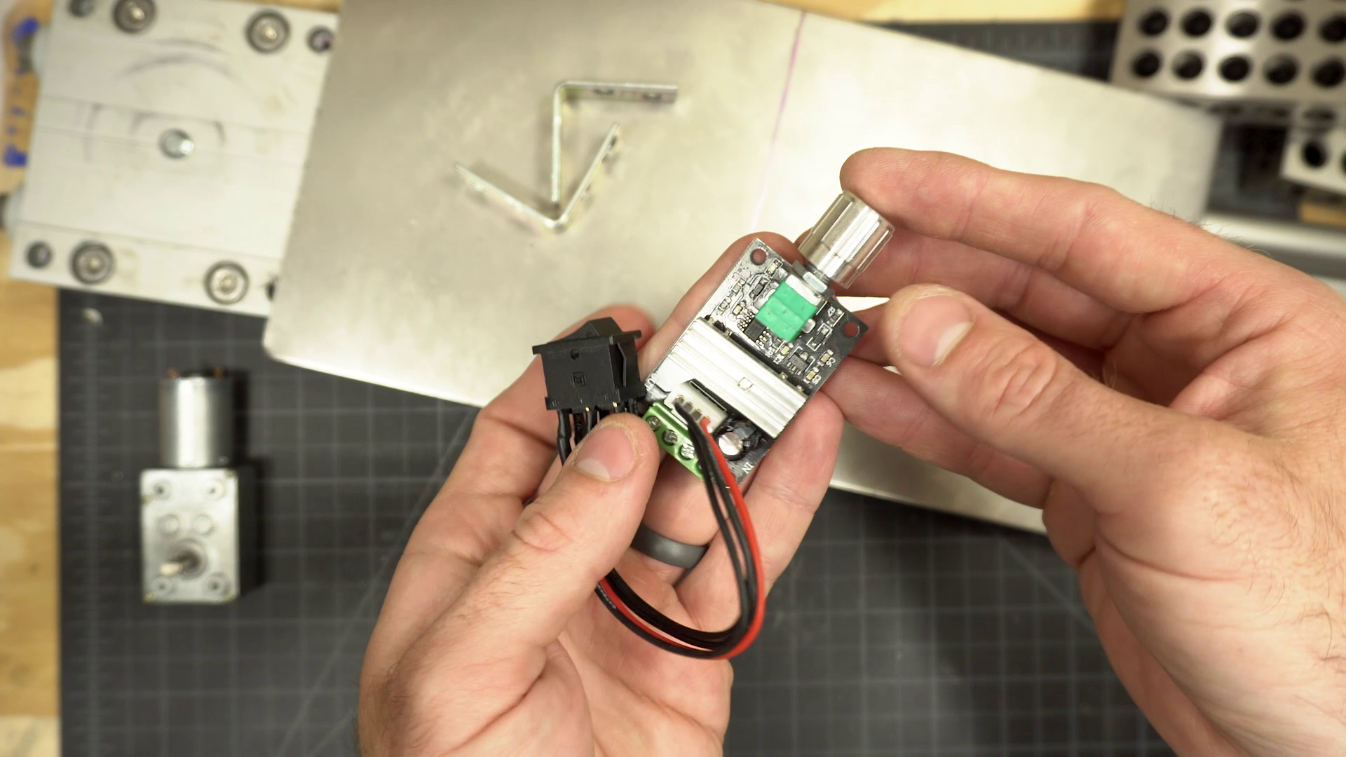
The main components of this project are an Igus railing w/ a sled, a small or scrap piece of 16guage sheet metal, a small 1rpm DC motor, a dimmer control knob to control the motor’s direction and speed, a small plastic box to house the motor controller in, some female wire connectors, a couple pulleys, a length of timing belt, a small battery to power the whole thing, some nuts, bolts, and other hardware, and a small tripod head. A list of everything I used in this project is at the bottom of this page, and as of this video all the materials for this project cost right around $250.
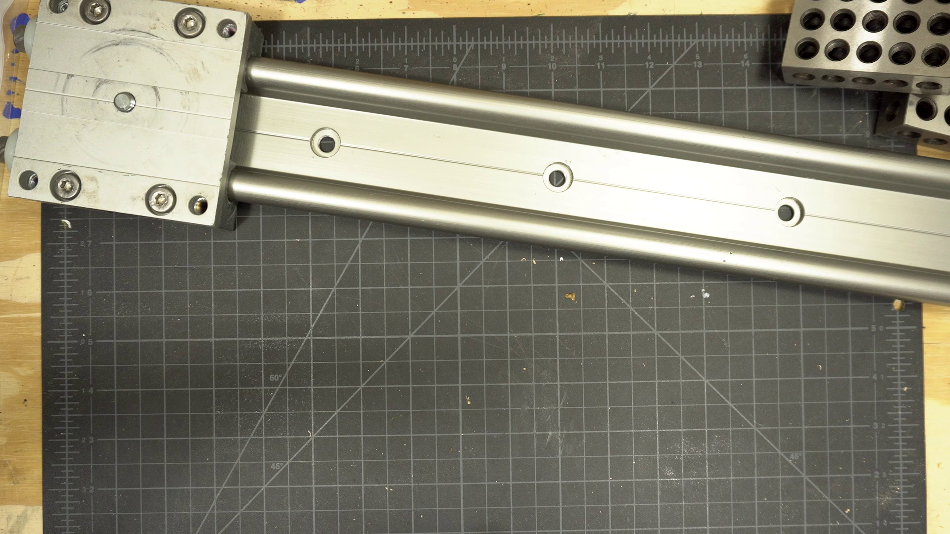
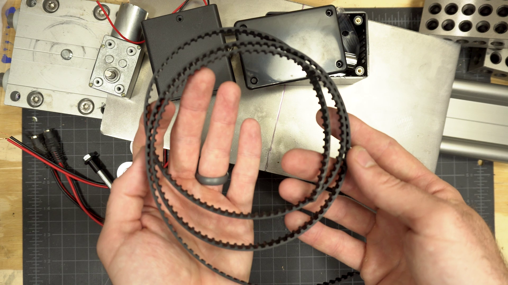

A quick note - I originally bought a 36” Igus rail slider like 9 or 10 years ago, but I found that it was too large and too heavy to be a practical slider for most situations, so I cut it down to just under 2' to make it more portable but still allow me about 18” of usable motion. But you can make one however long you want, and you could even adapt these plans to fit your own slider if you currently have one. Regardless of what size you go with just be sure to get enough timing belt to cover double the length of the slider. With all that being said let’s get started.
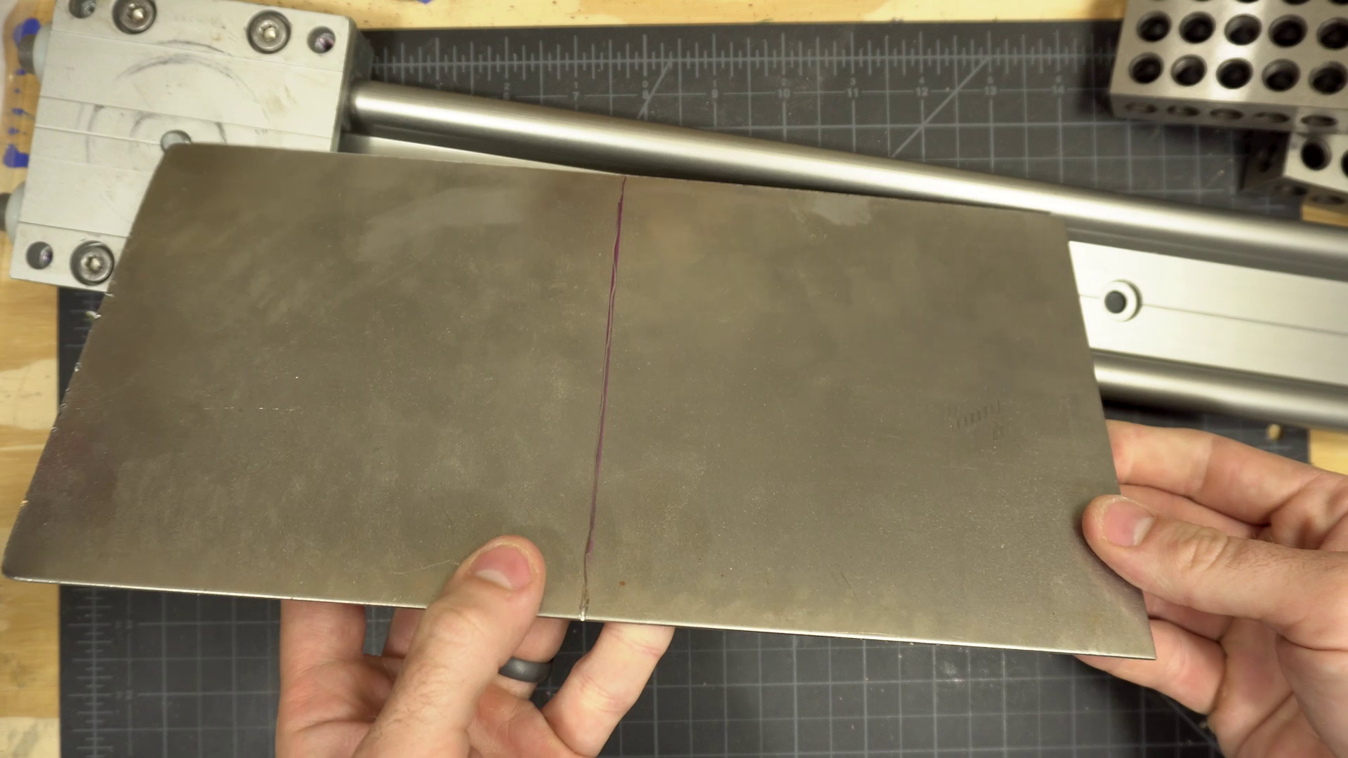
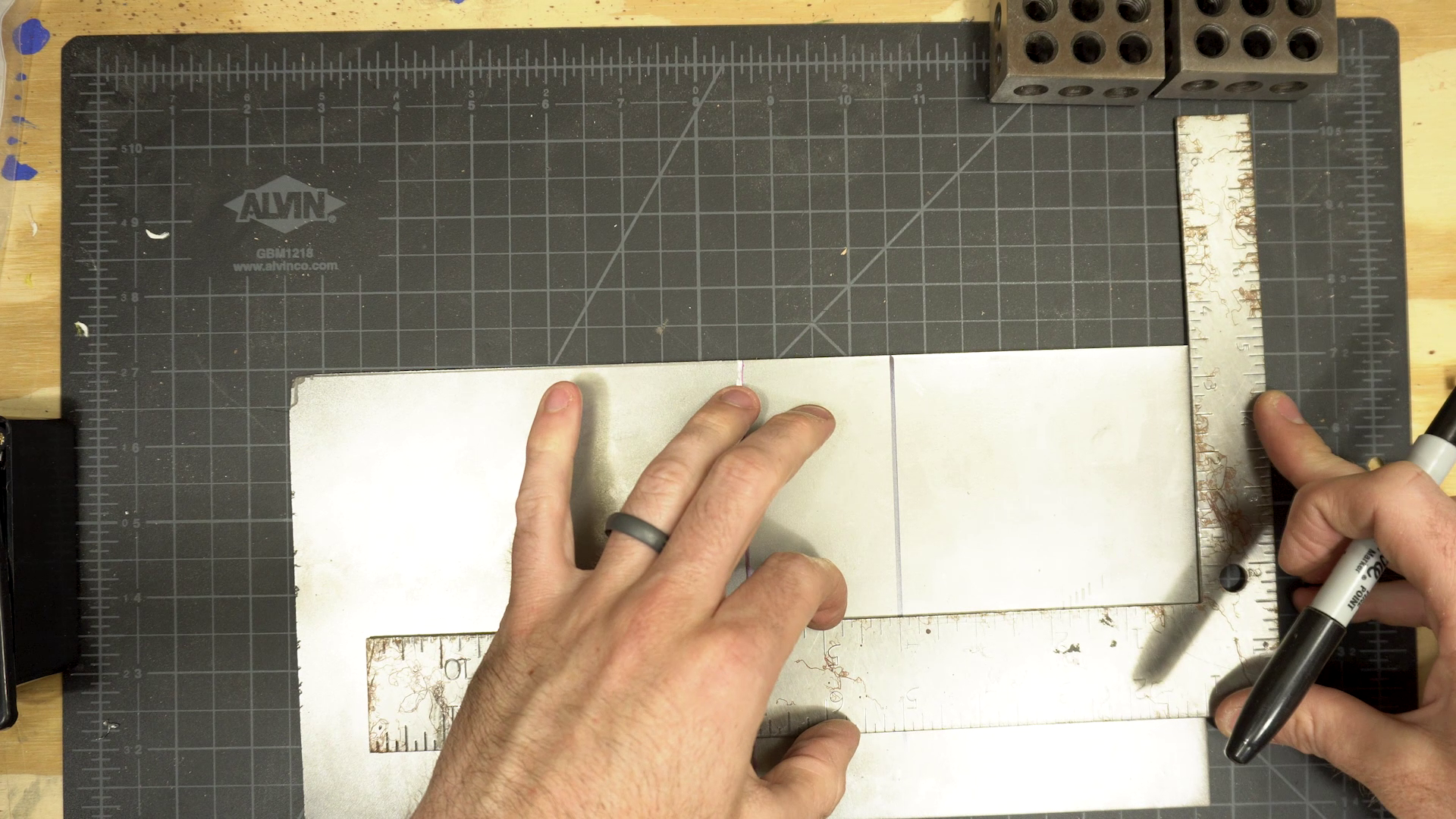
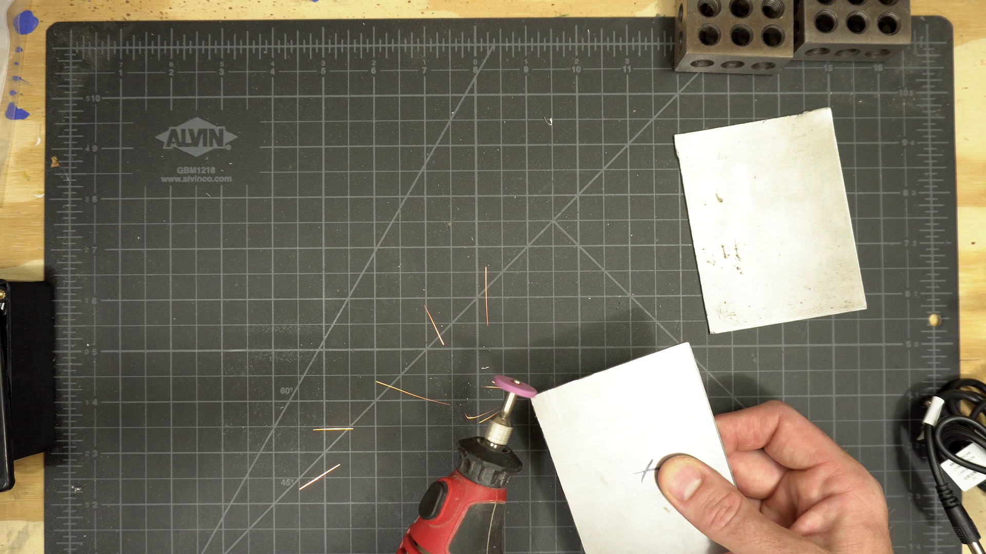
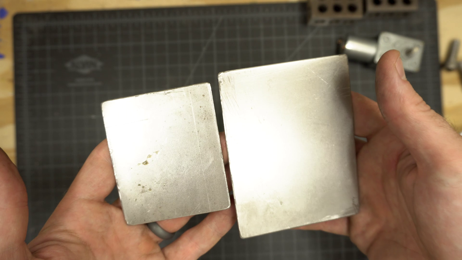
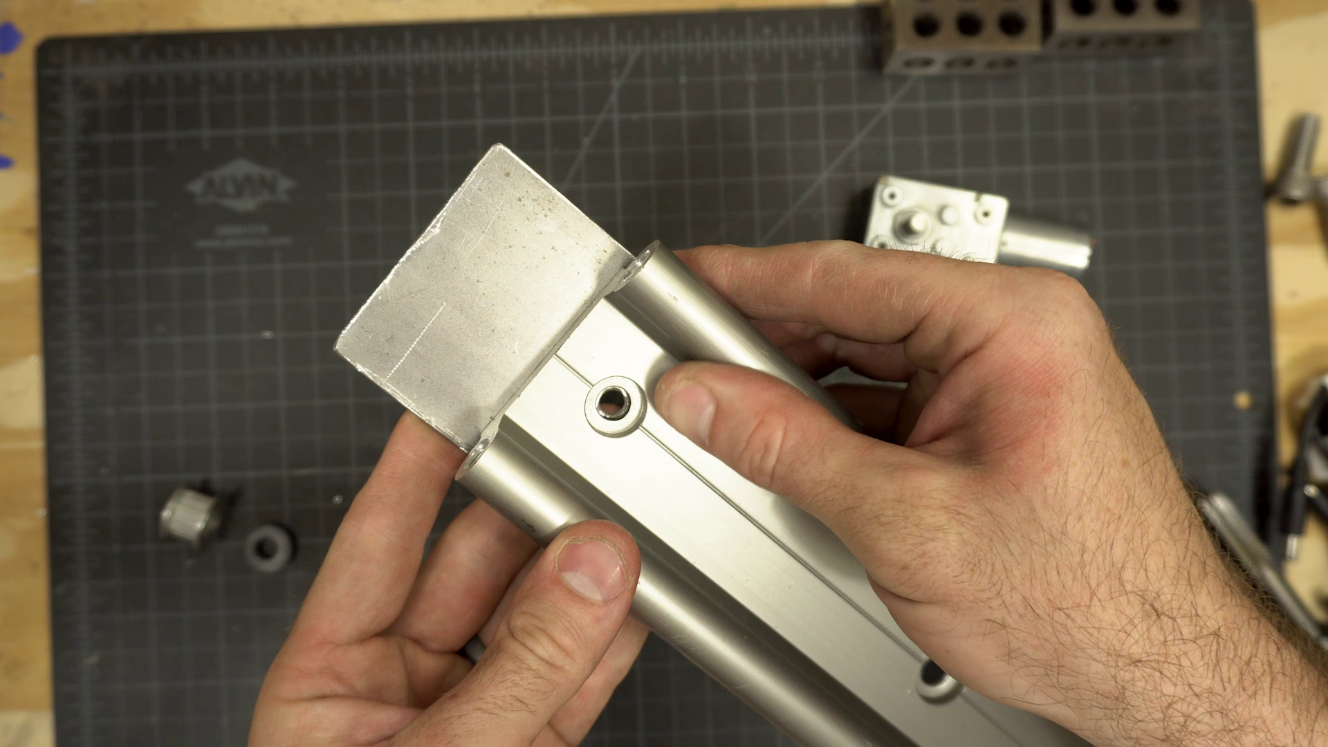
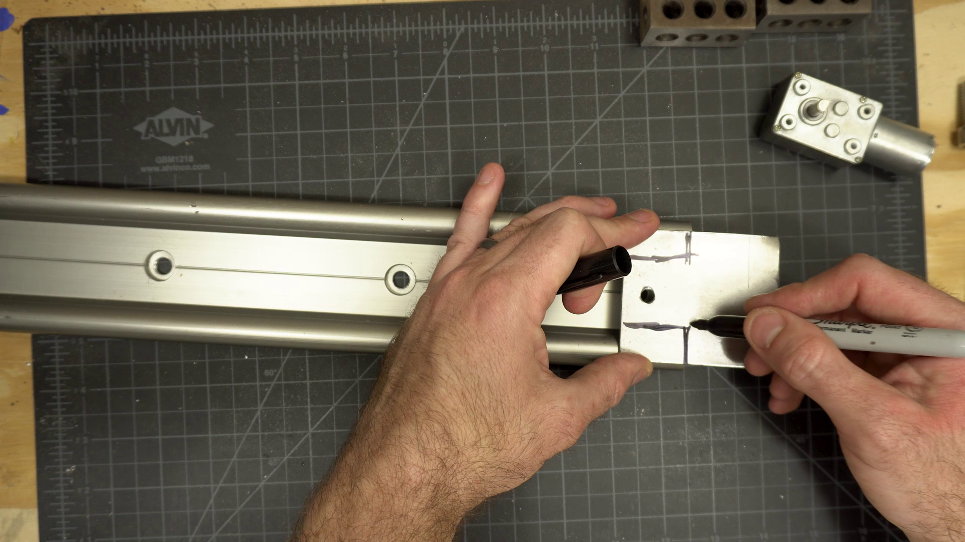
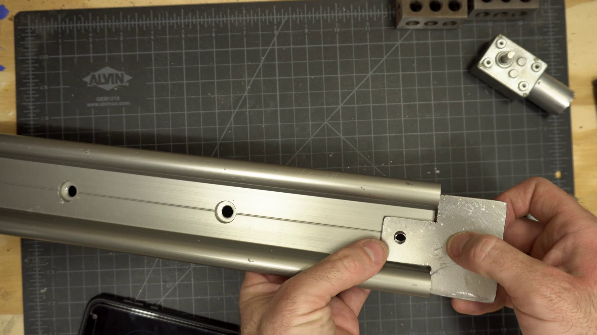
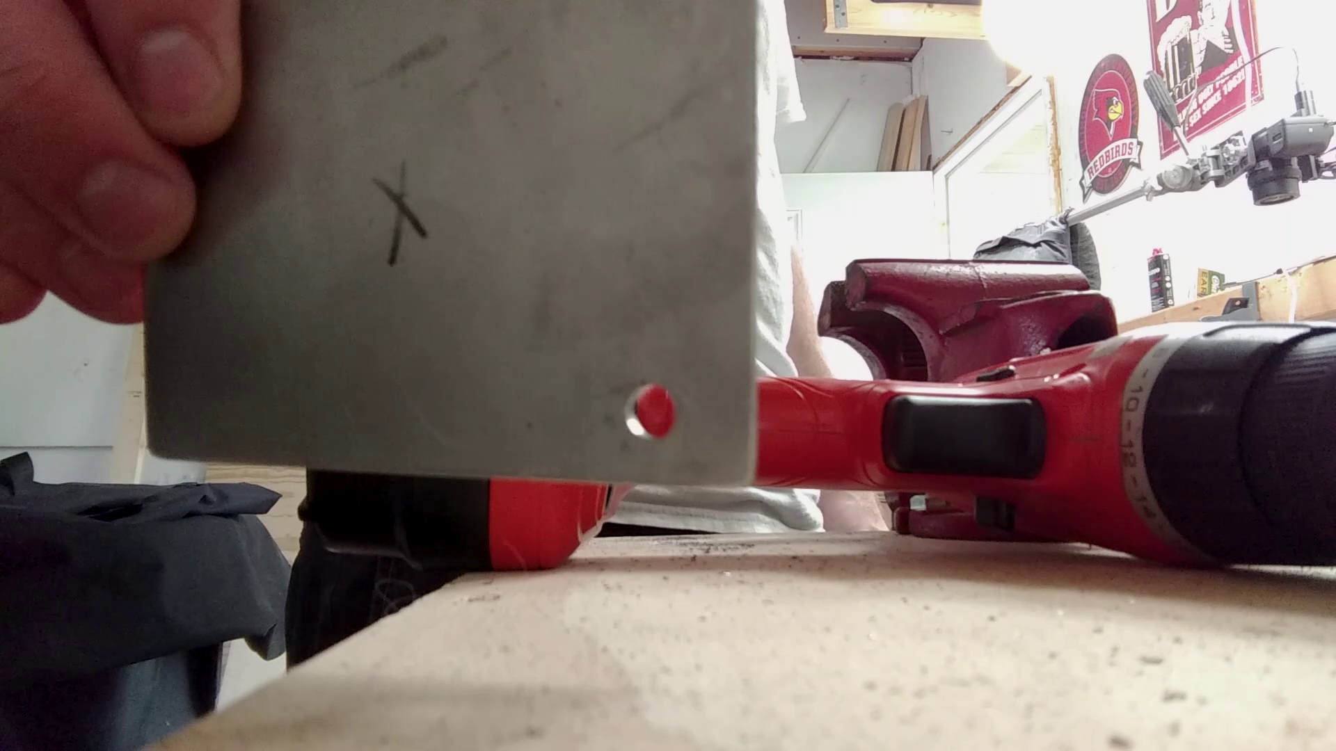
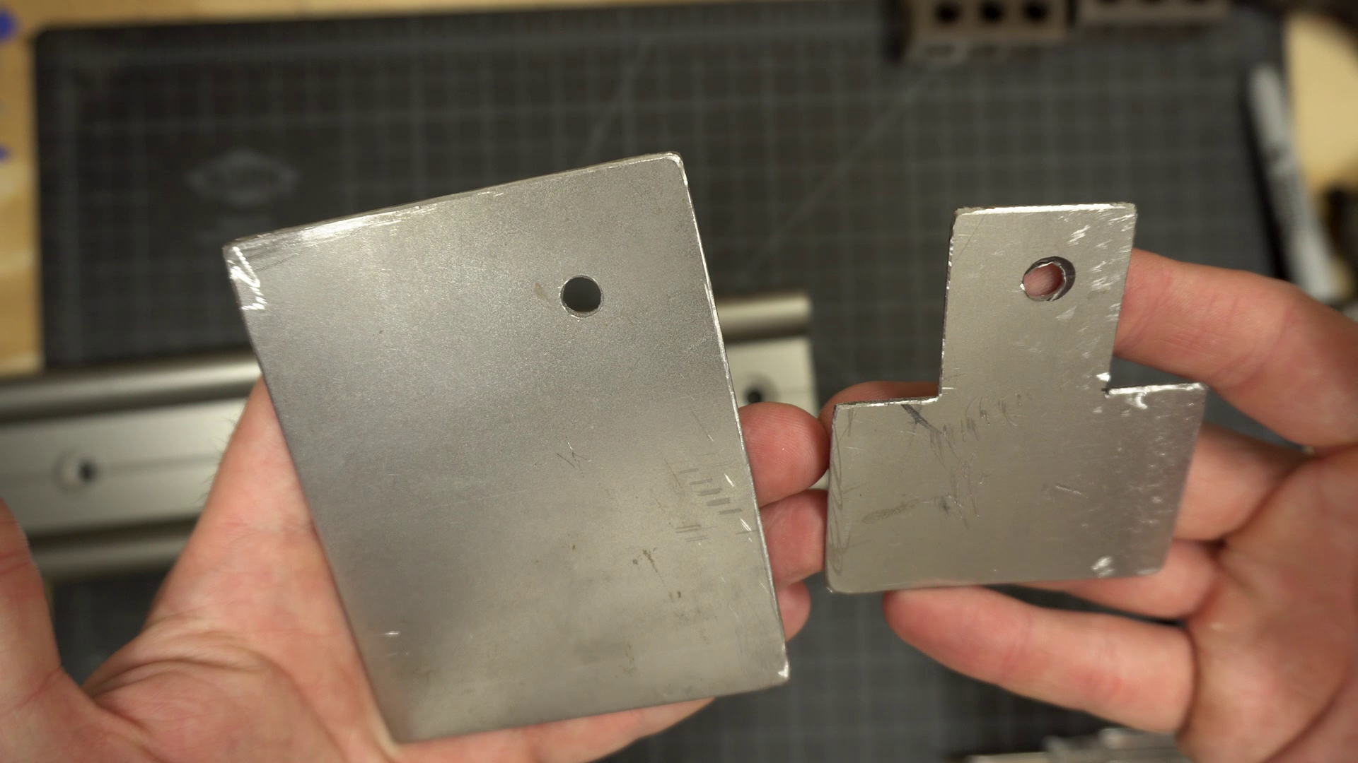
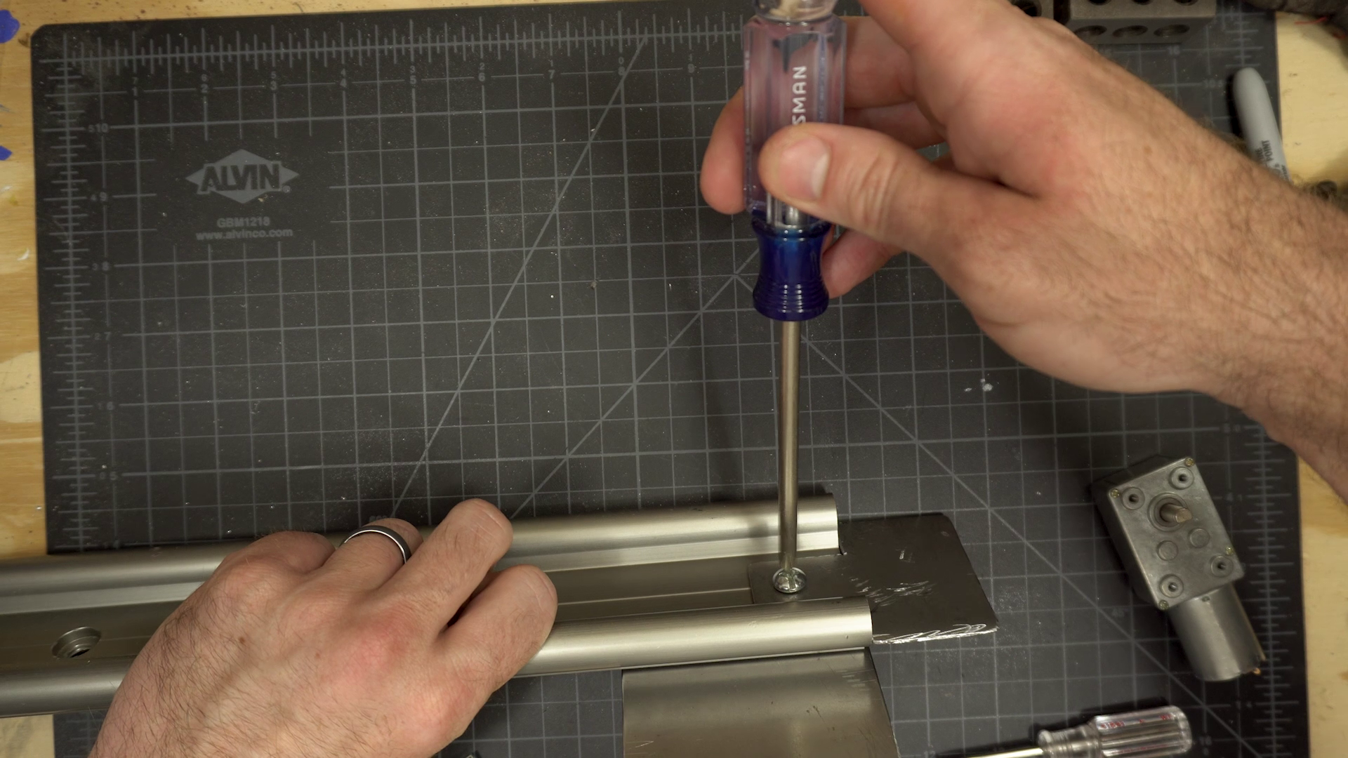
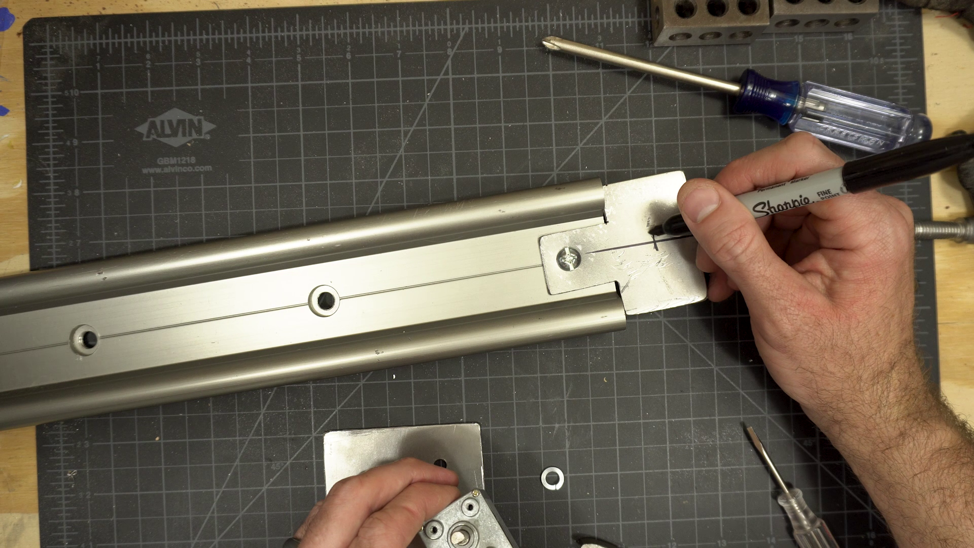
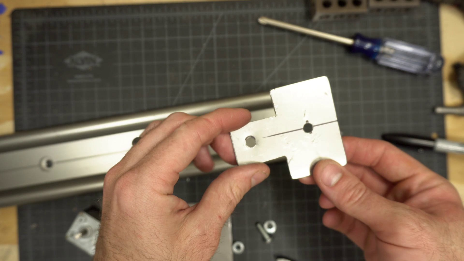
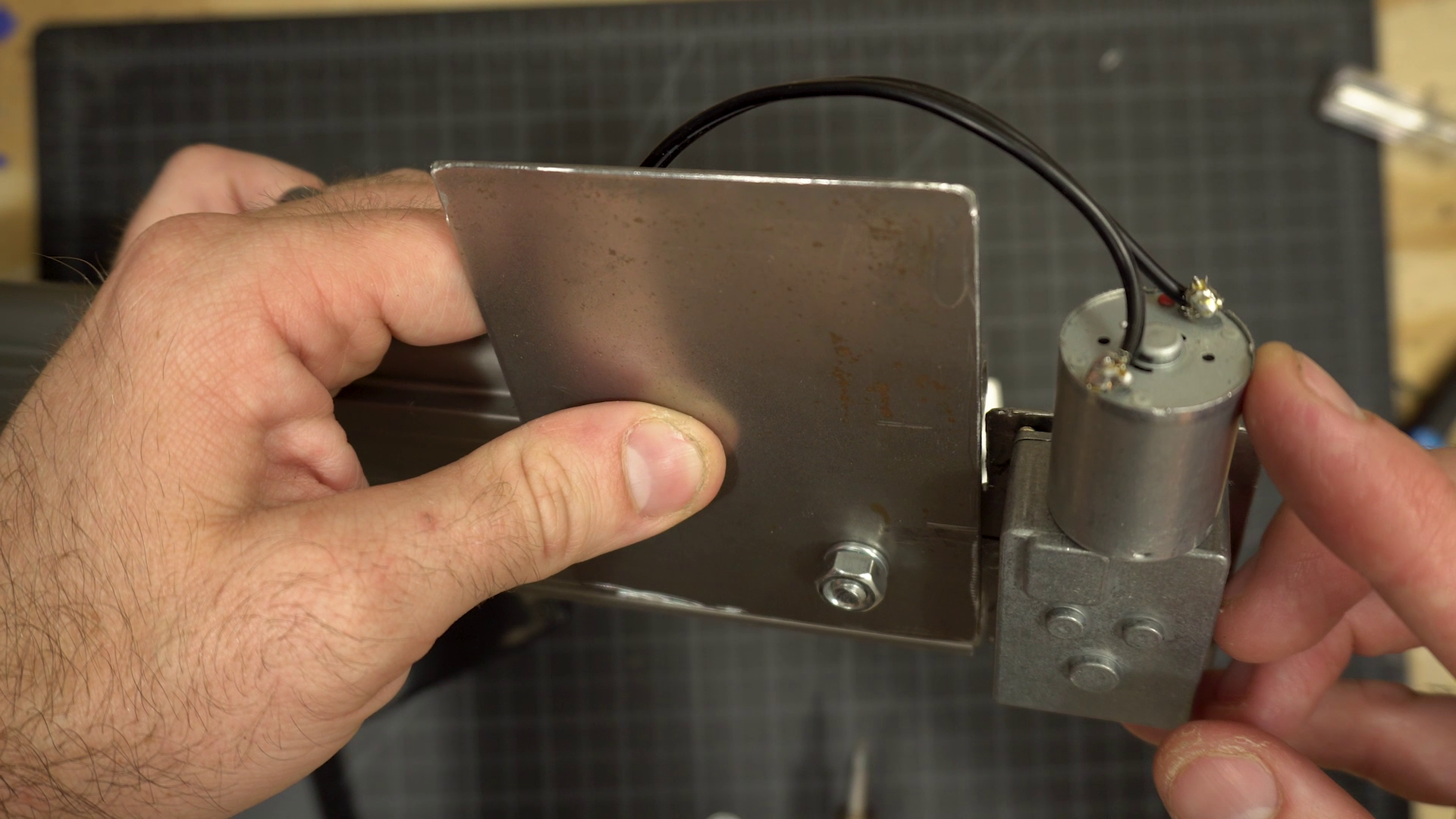
The first step is to measure out a 3x6” rectangle, and a 3x2.5” rectangle on your sheet metal, and cut those out with a hacksaw. Then you’ll want to grind the sharp edges down with a dremel or a file. The smaller piece will be used to attach the motor to the slider, and the larger piece will be used to hold the battery and motor controller box. We want to drill a hole in the small piece so lay your slider on top, line it up, make a mark, and then drill a ¼” hole. This piece will actually sit on top, so we need to cut a few notches so it will sit flush within the slider channel. Make a couple marks where the slider channel is, and then line up your holes and mark how far in the piece will sit. Then cut those corners out and you should have a small piece that will sit nicely within the slider that we can mount the motor to. Set that aside for right now and get the larger piece we cut. We will mount this piece under the slider using the same hole as the motor mount, so mark and drill a hole in the corner of this one. Now you should have both pieces ready to mount - go ahead and test it out with a ¼” bolt and nut - I used a lock washer on the bottom to keep some additional tension - tighten everything up and make sure it fits and that the motor still has enough room to be mounted before you go any further.
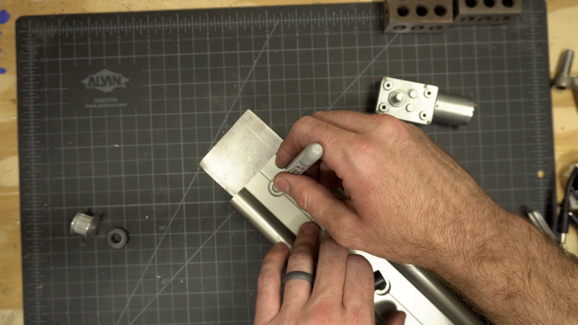
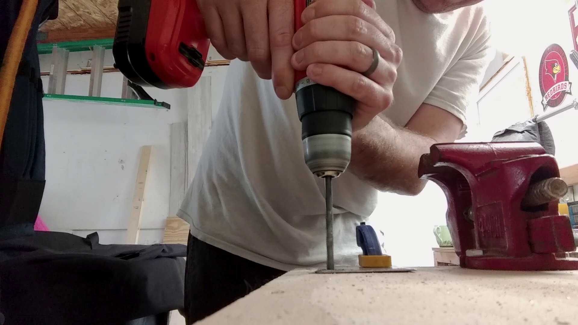

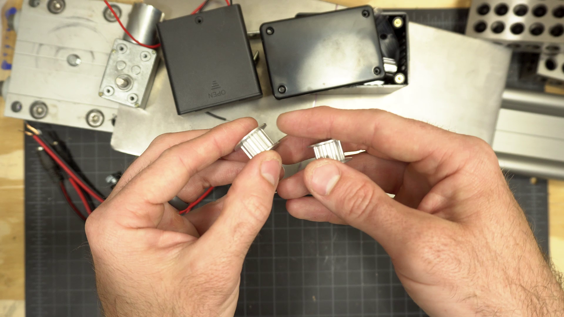
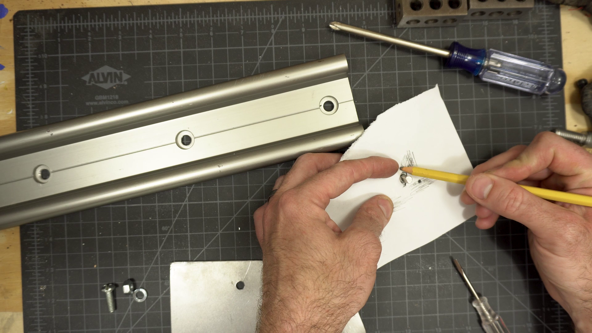
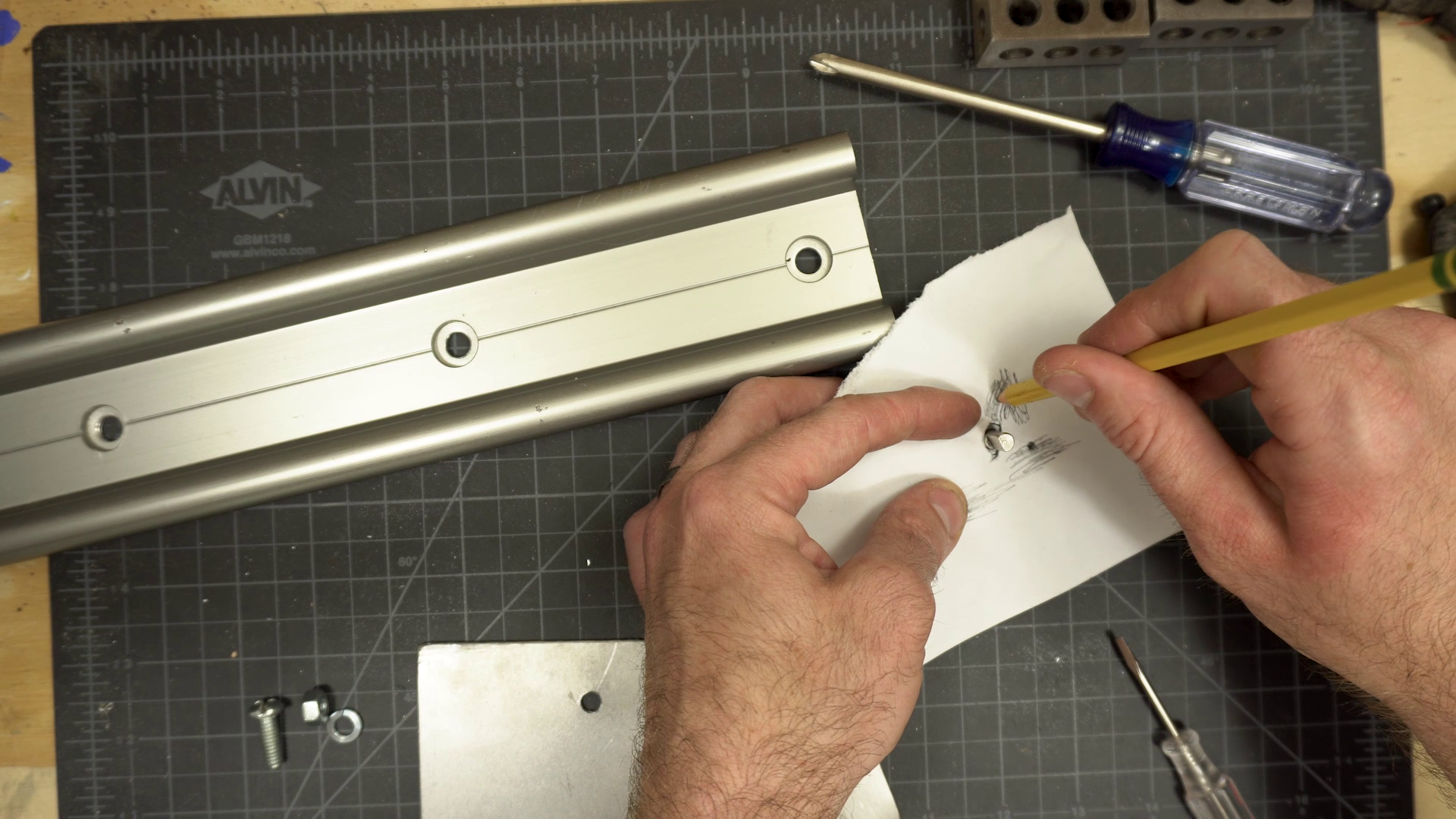
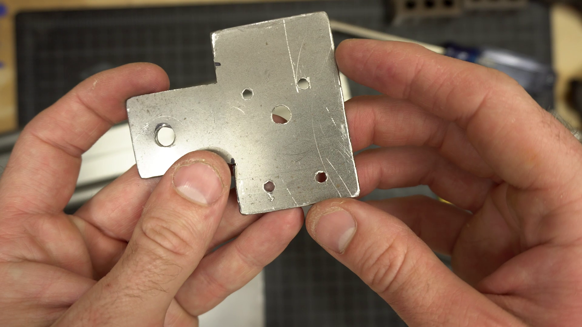
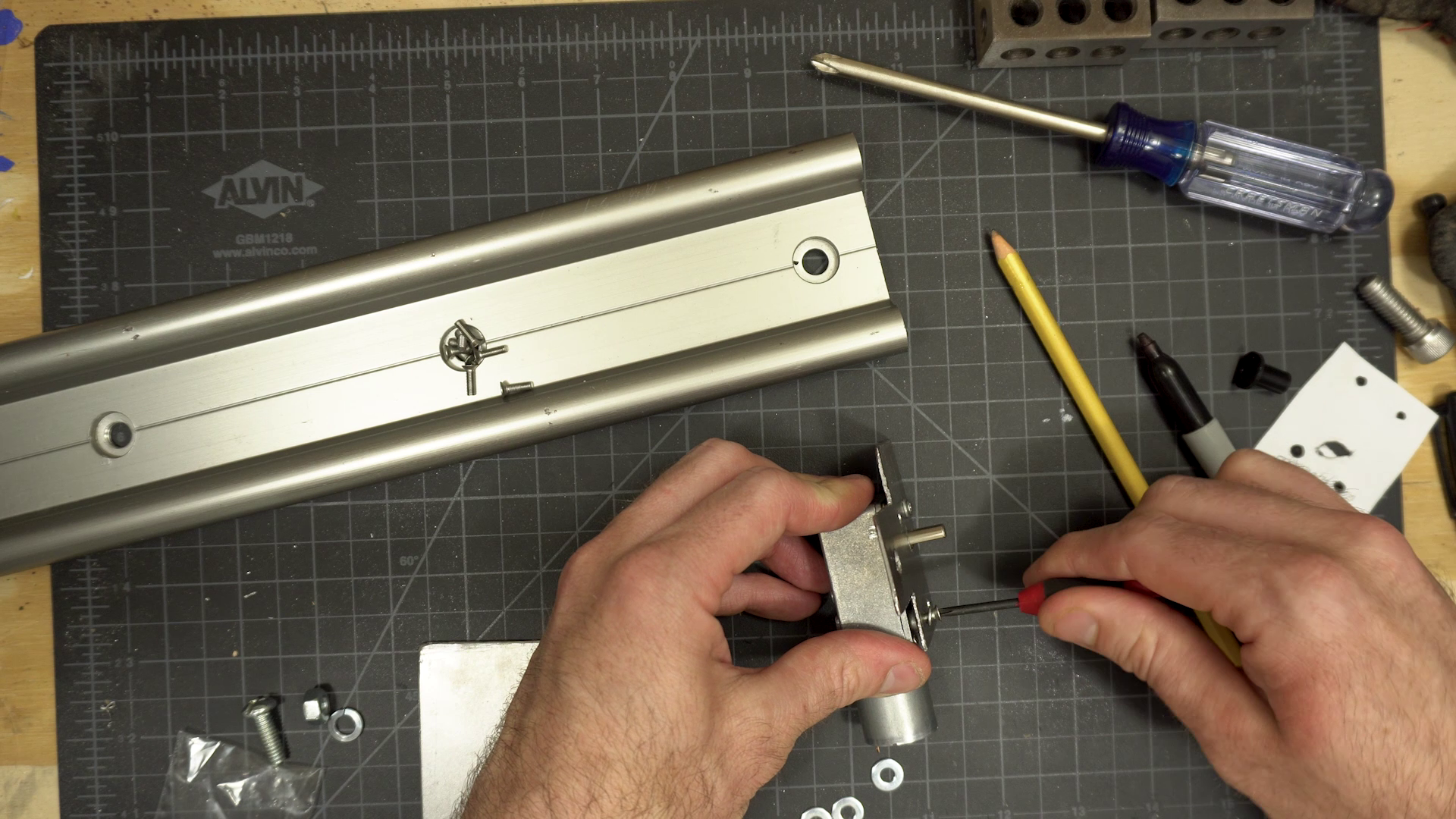
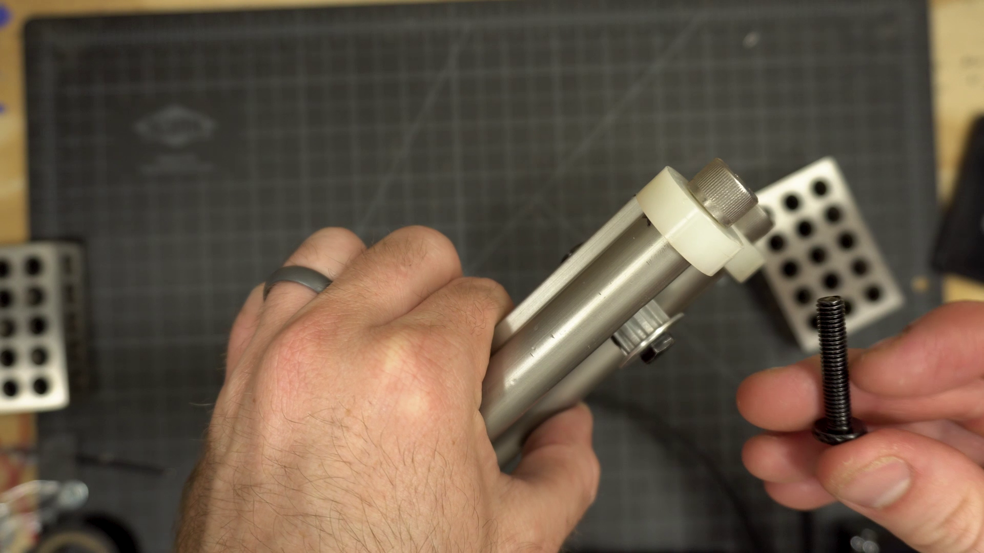
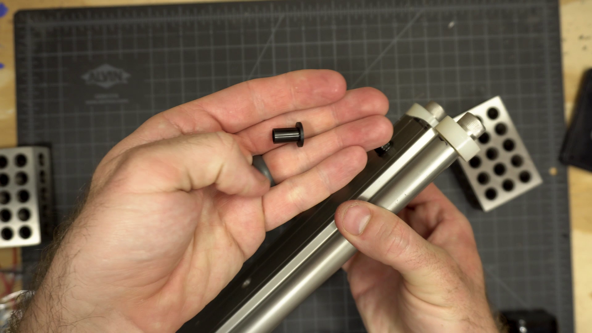
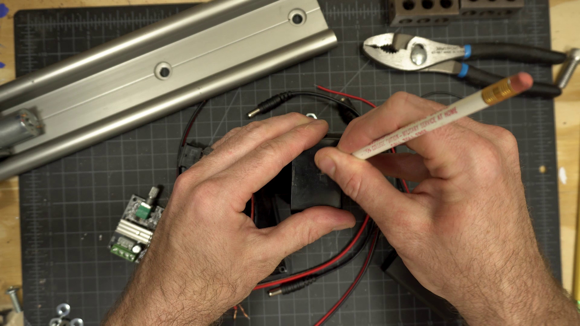
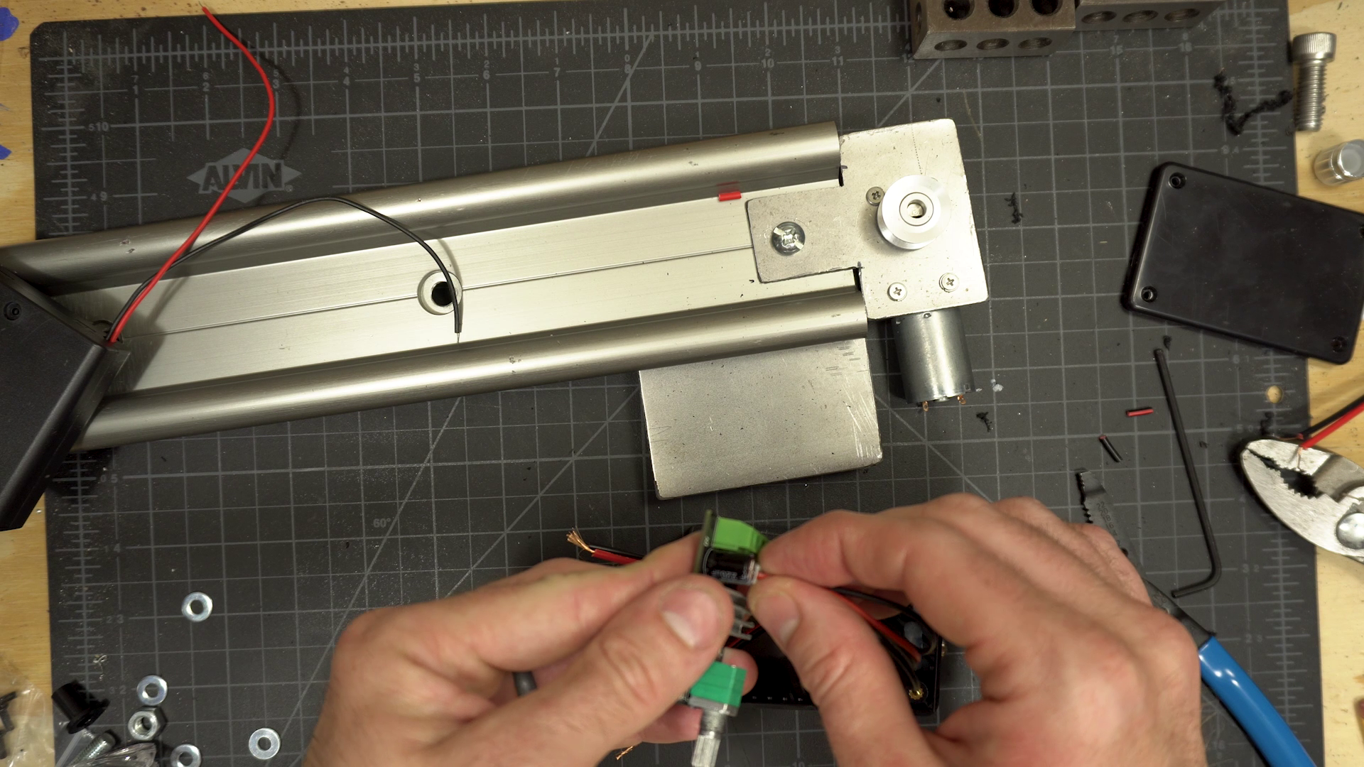
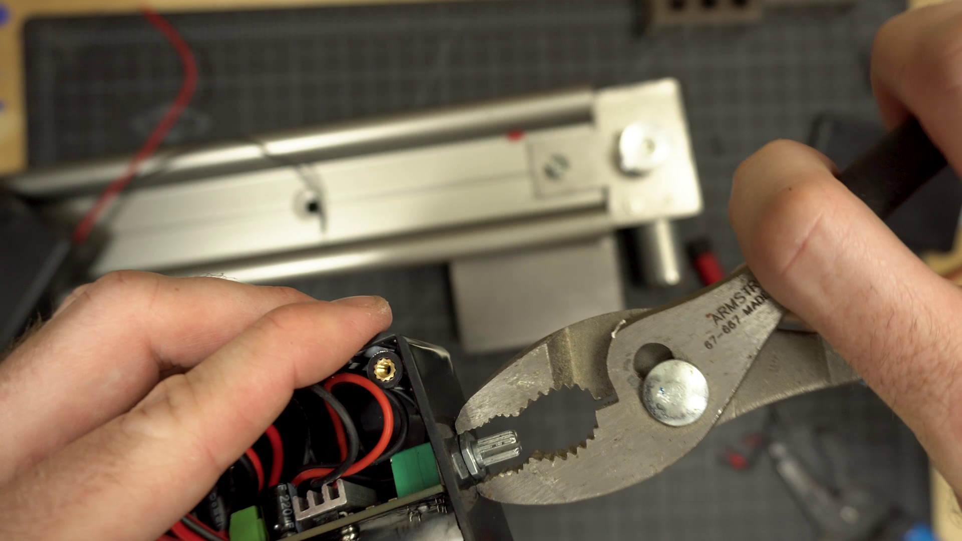
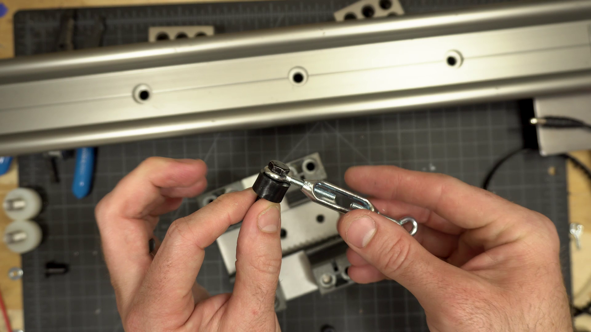
We want to drill a ¼” hole for the motor shaft in the middle of the small piece - so use a ruler or a tape measure to find the center, make a mark, and then take that piece off and drill the hole. Now we need to drill some holes to mount the motor - the easiest way to do this is to grab a scrap piece of paper, put it over the motor and shaft, and then using a pencil rub the corners until you find the holes, and use the pencil to poke a little hole in the paper. We’ll use this as a template when drilling. Because this isn’t very precise I marked a few areas on the motor mount piece just so I knew where I needed to be drilling. Then drill those holes - we don’t want these very big, I think I used an ⅛” bit. Check to make sure everything lines up and then attach the motor with 4 small bolts. I just took my motor into the local hardware store and found some that fit - I believe they were M3 sized. Once that’s mounted go ahead and bolt everything back onto the slider and then use a smaller allen wrench to attach one pulley to the motor shaft. For the pulley on the other side use a small bolt and a nylon bearing and attach it that way. The nylon bearing should sit flush on the slider and allow the bolt and pulley to move freely.
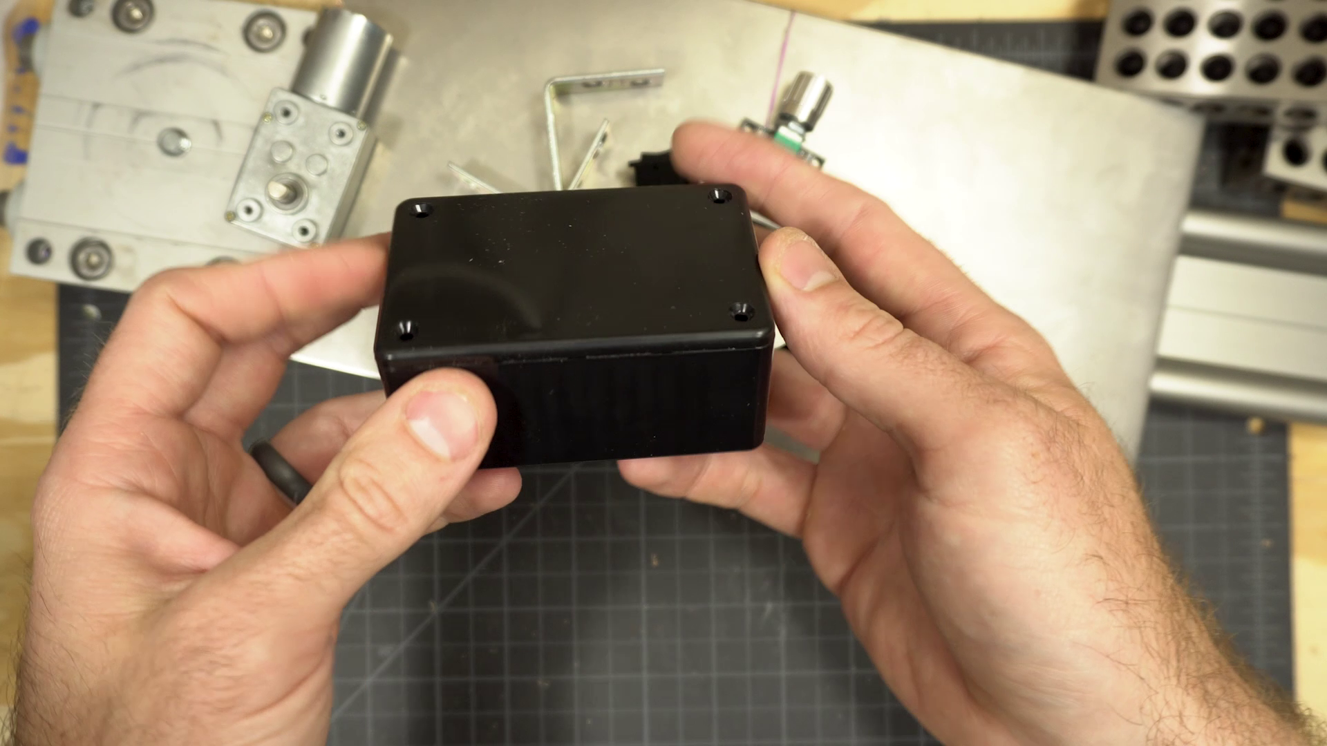
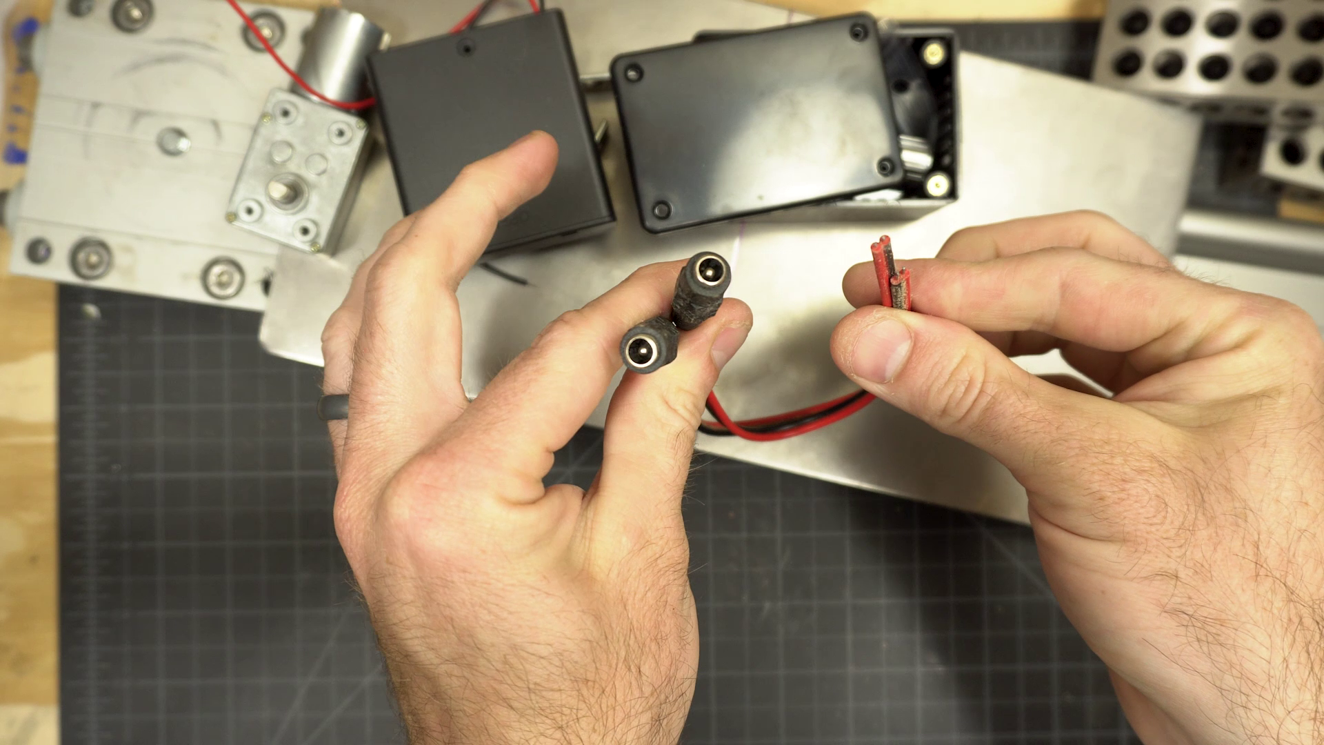
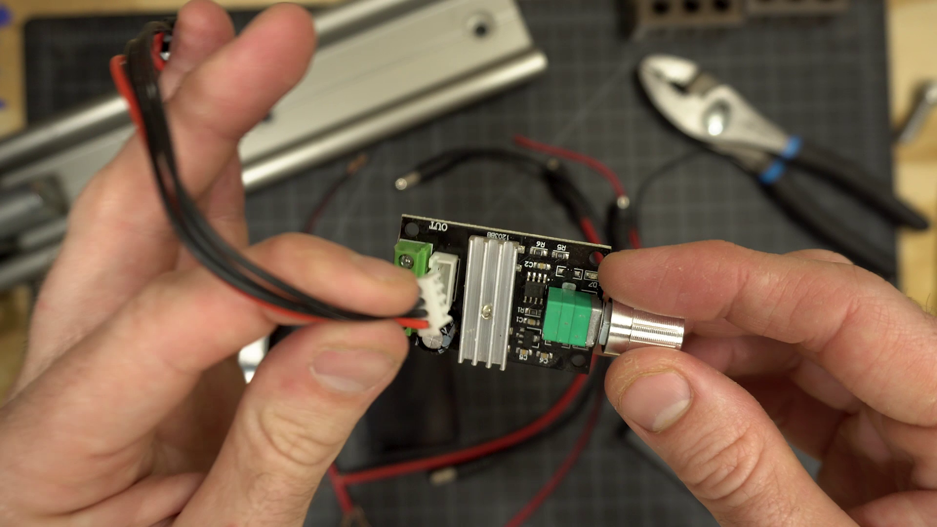
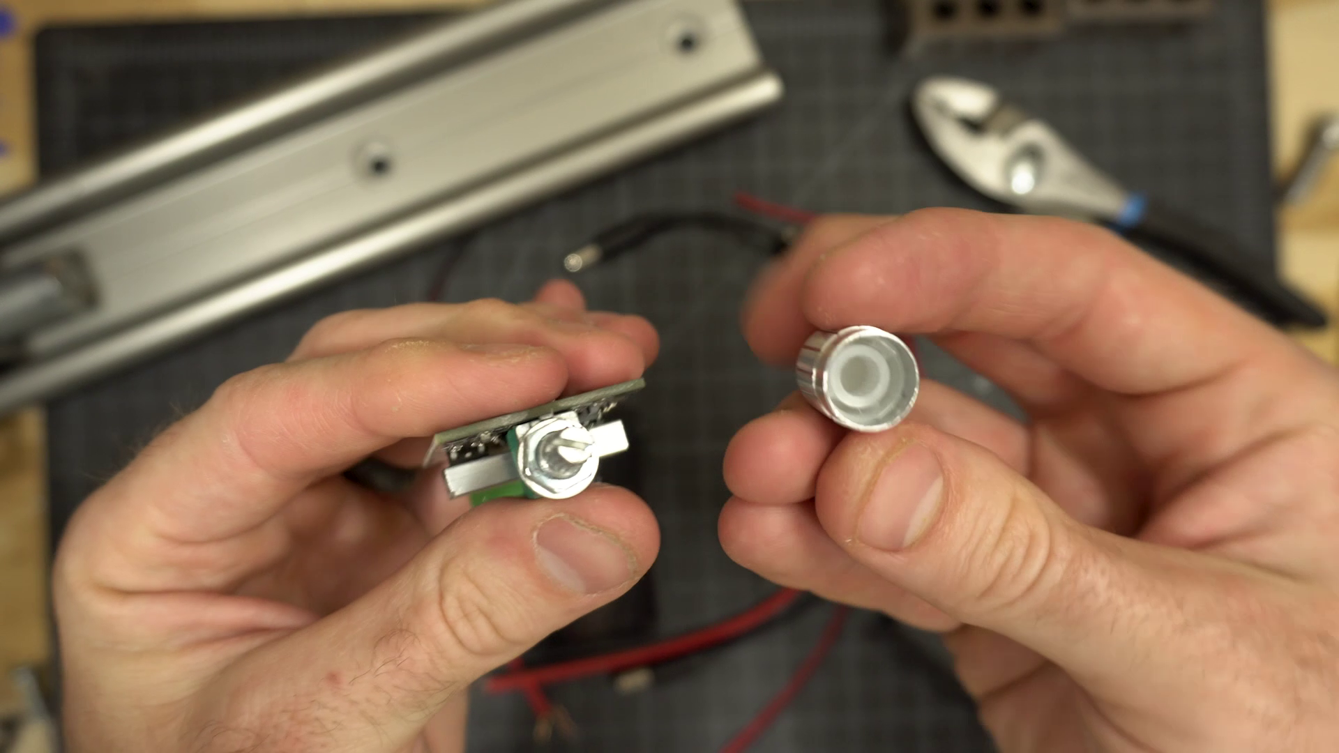
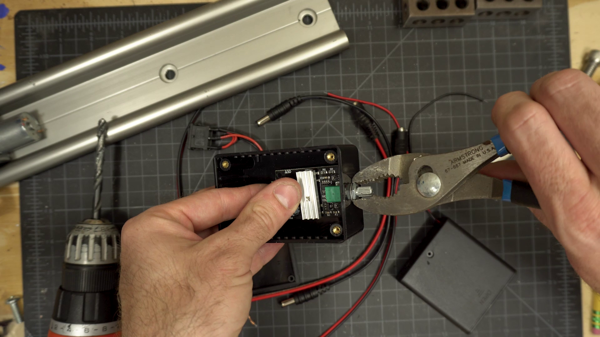
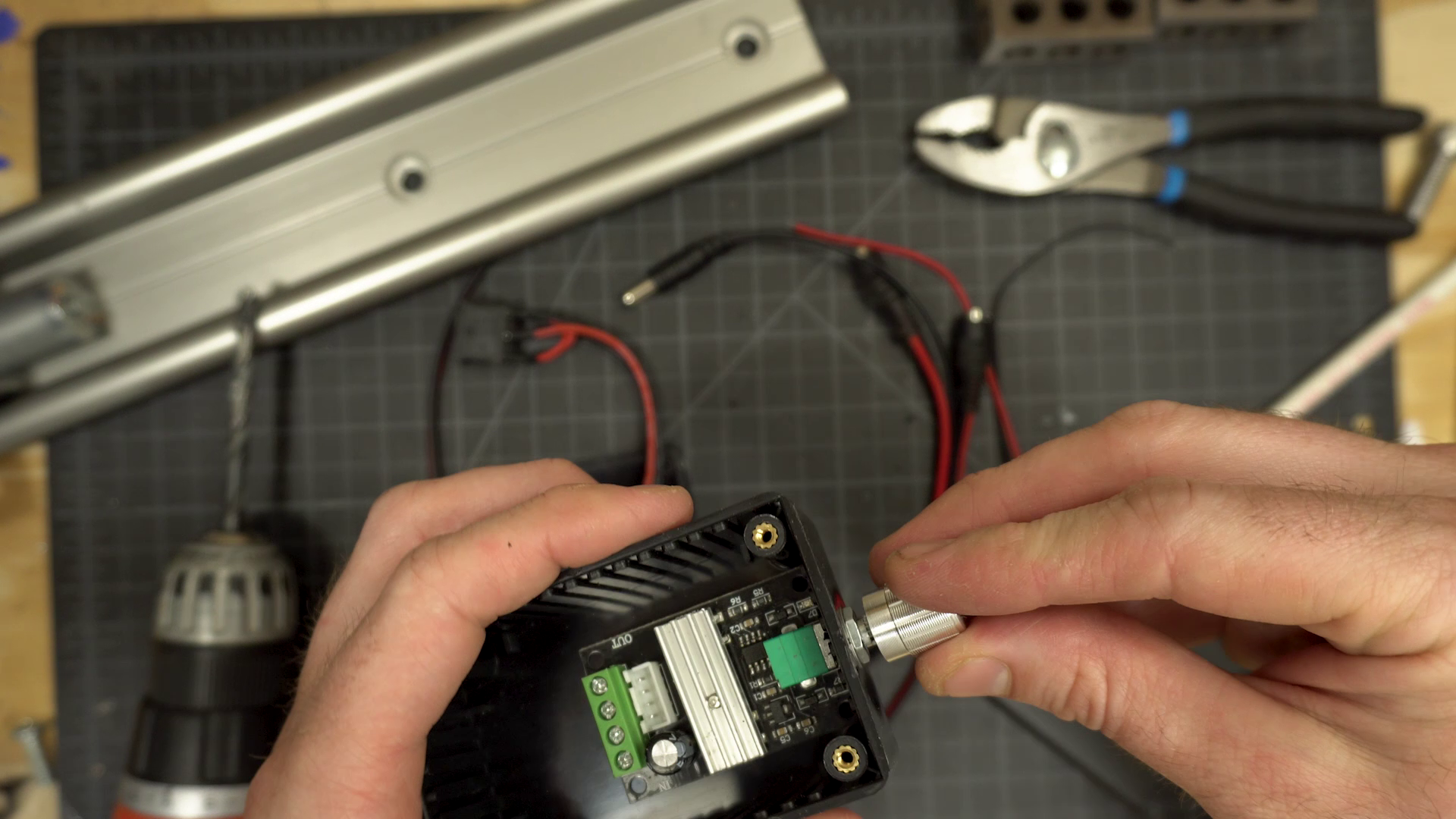
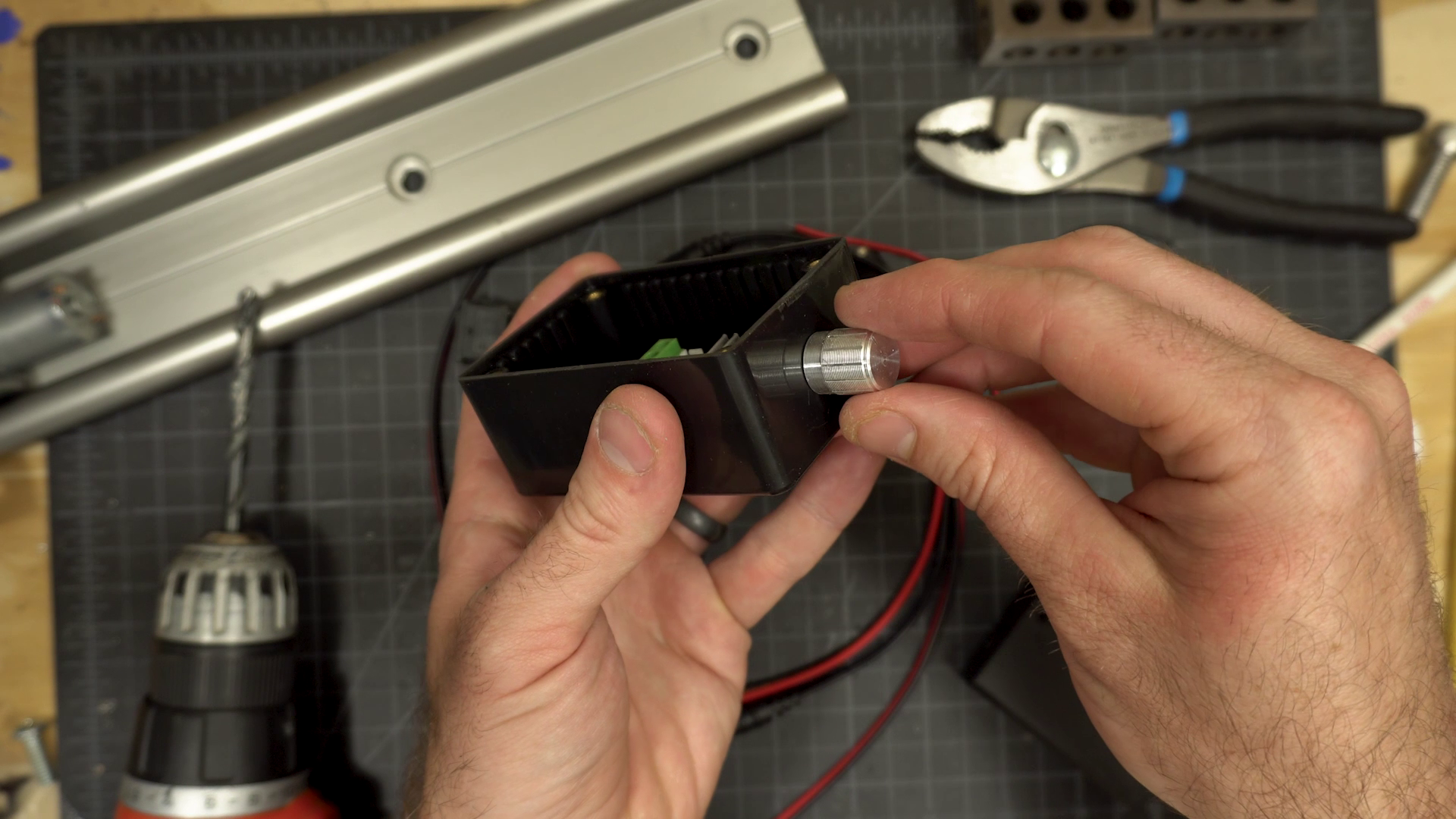
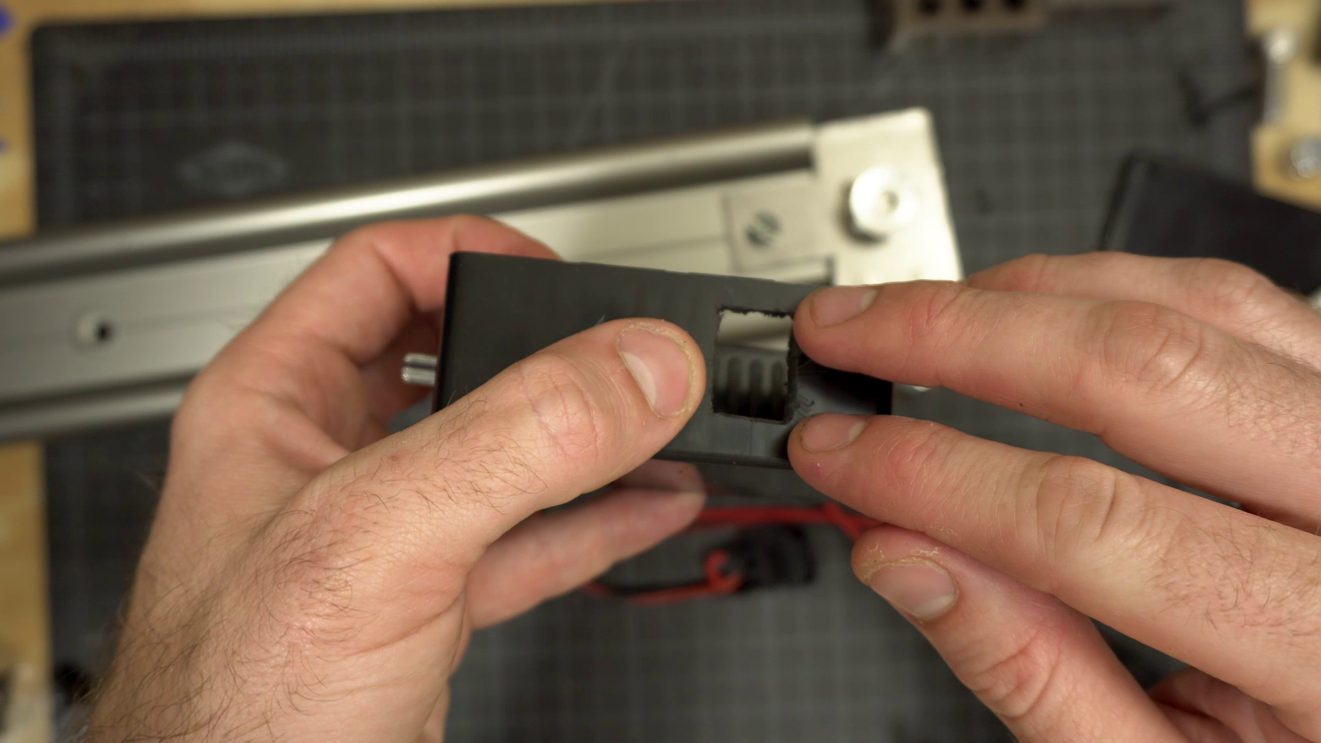
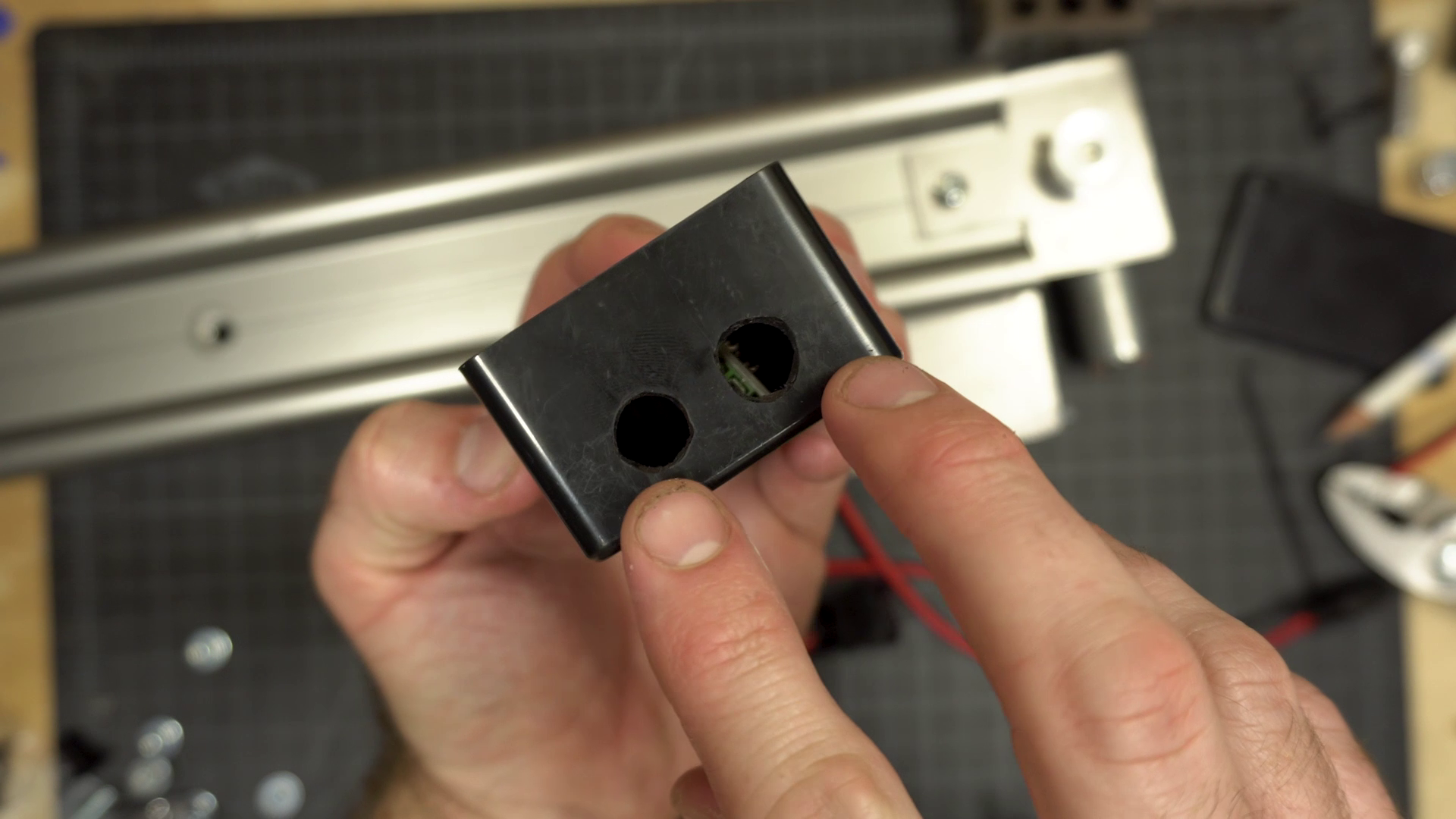
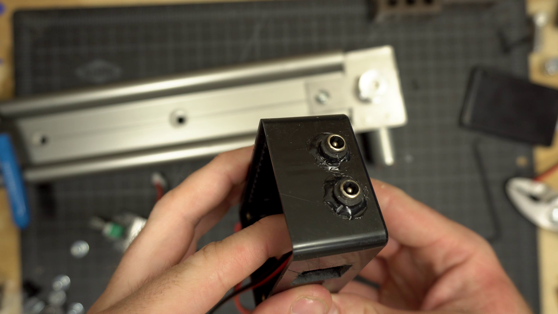
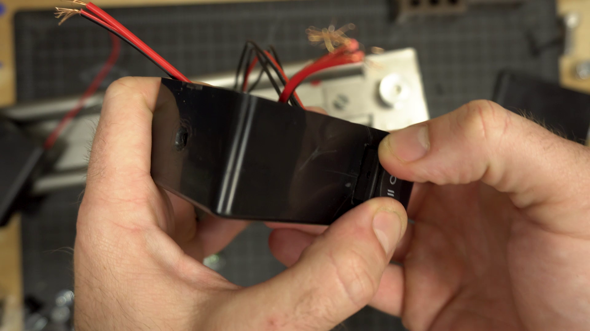
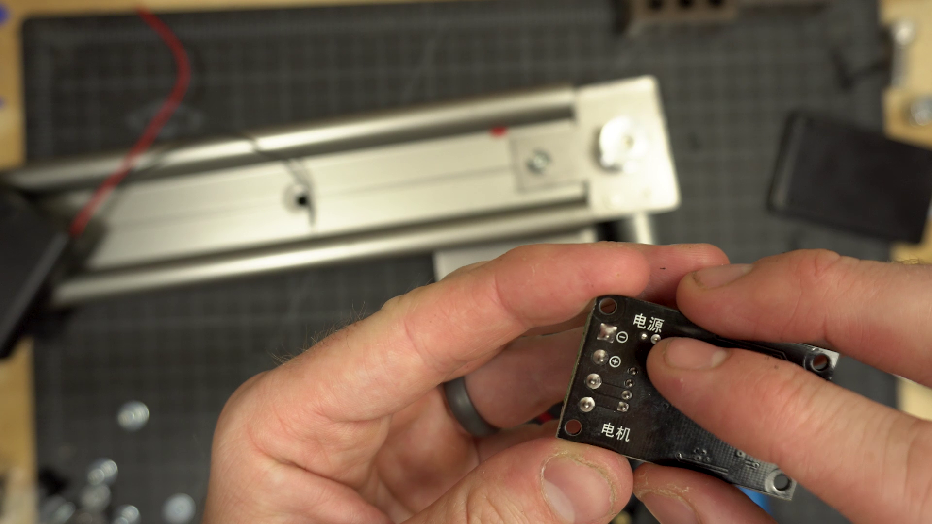
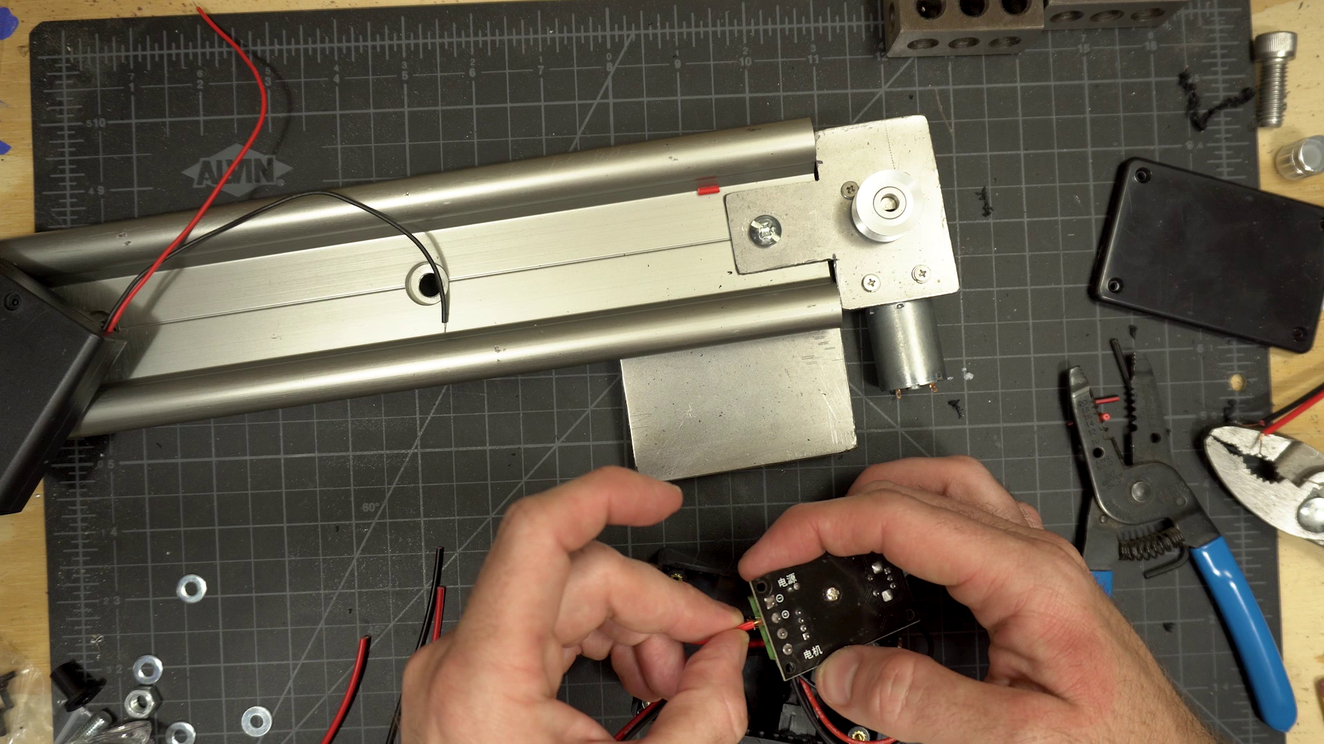
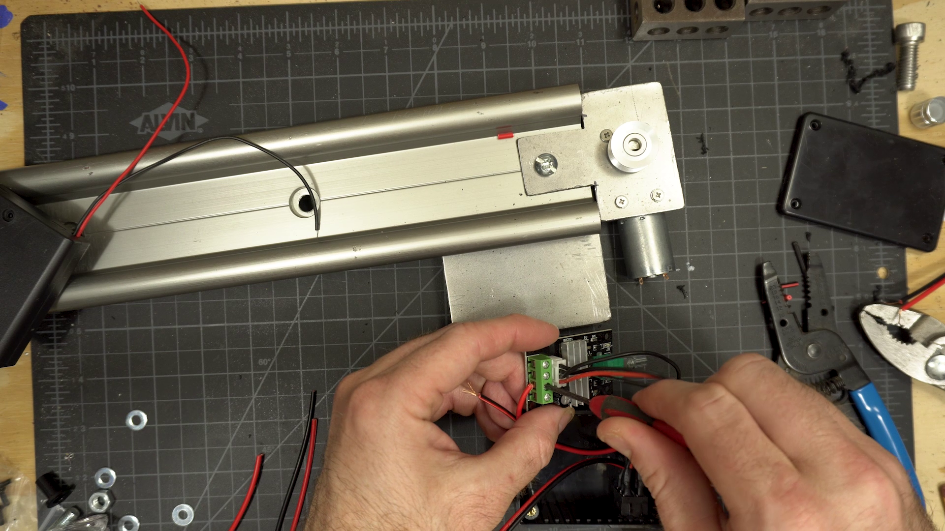
Set all that aside for now and grab your plastic box, motor control switch, and female cables. Prep your motor controller by removing the directional switch module, the main knob, and the nut. This box fits everything but it’s a bit tight, so we want the knob to come out the end, not the side. Make a mark in the middle of the one end, and drill a ¼” hole. Feed the bare knob through the hole from the inside, use the nut to secure it, and the attach the knob to make sure it all fits. Then take it all off, and we want to make a hole for the directional switch - I wanted mine on the outside so it wasn’t tight against the motor - I drilled a couple small holes next to each other, and then filed it into a rectangle. Then we want the power in and out from the opposite side as the main knob, so drill 2 holes there, I think I used a ⅜” bit. Then grab your power cables, and using a little hot glue attach them to the box. I used some more hot glue on the outside as well just for some added durability. Then cut your cables down so you have 3-4 inches to work with, peel them apart a little, and strip about ¼” off the ends. The switch should go on now because it actually needs to go over one of the wires - carefully wind it through, and then snap it into place. No we can attach everything to main control board. Attach the directional switch module back into the board. The power in and out are marked, just loosen the screws, feed the bare wires into the correct spot, and tighten back down. Now carefully put the board into the box, feeding the knob through the main hole, secure it with the nut, and attach the knob. Everything should snuggle nice and tight inside the box, then attach the top of the box. To power everything take your power cord, and cut one end off. Strip the ends, and then solder them to the correct connections on the bottom of your motor.

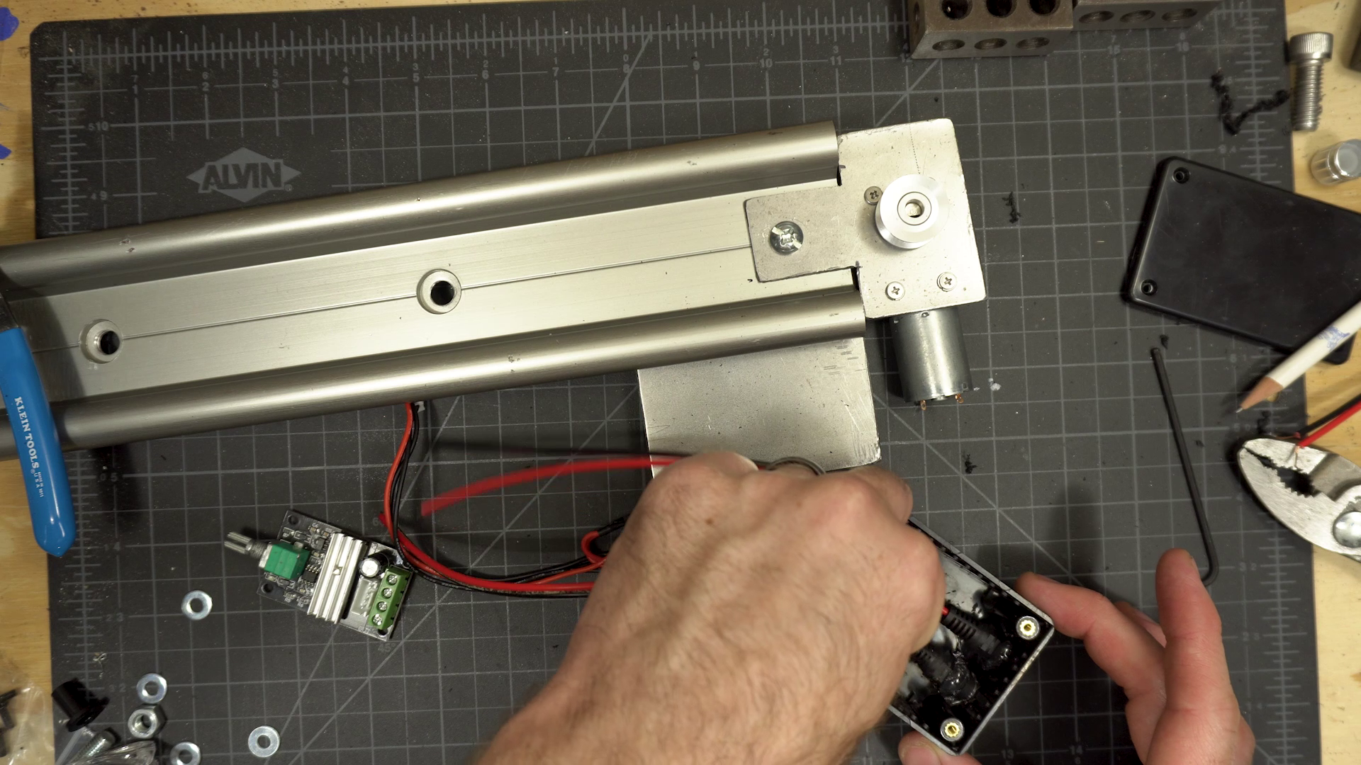


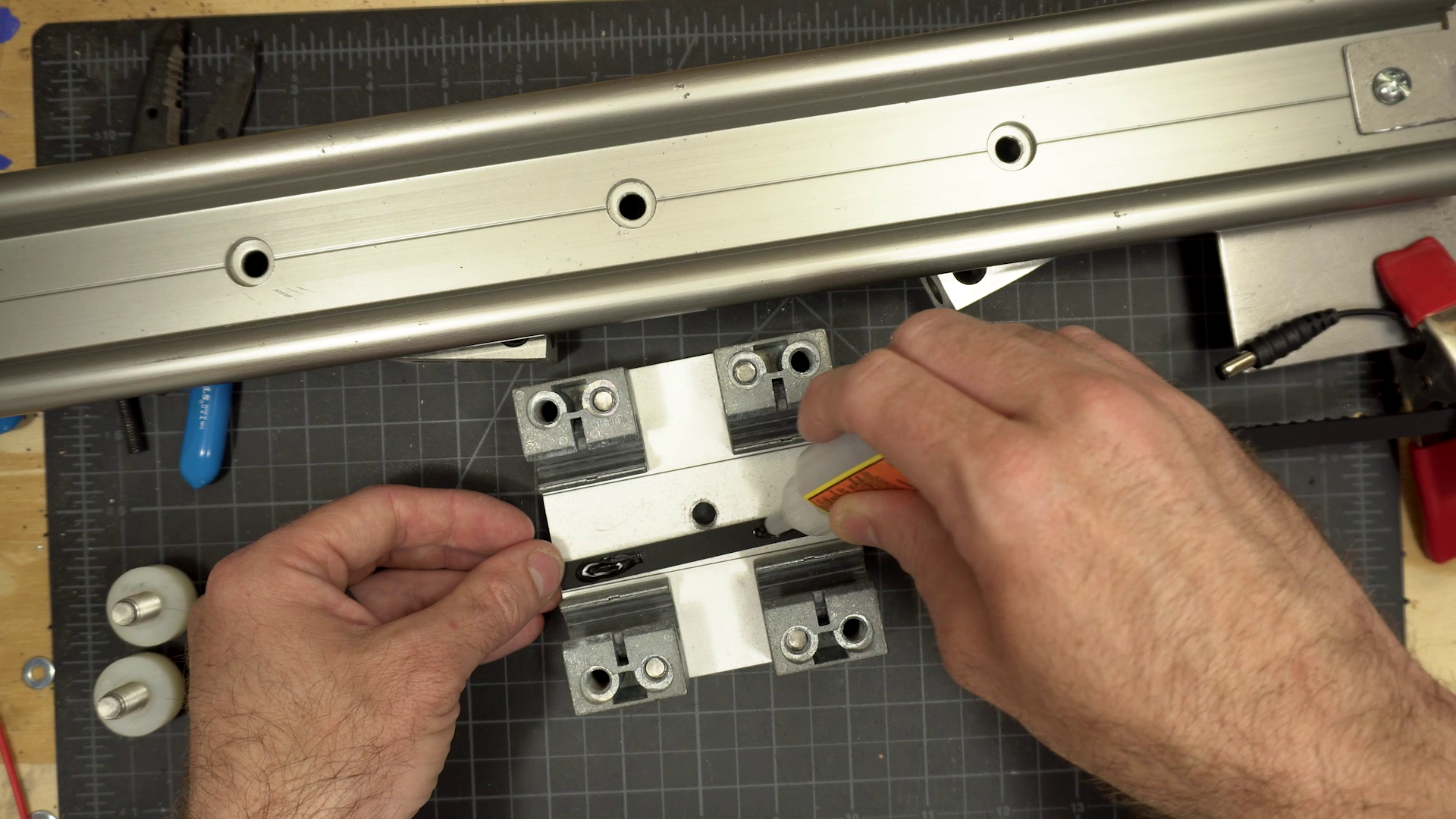
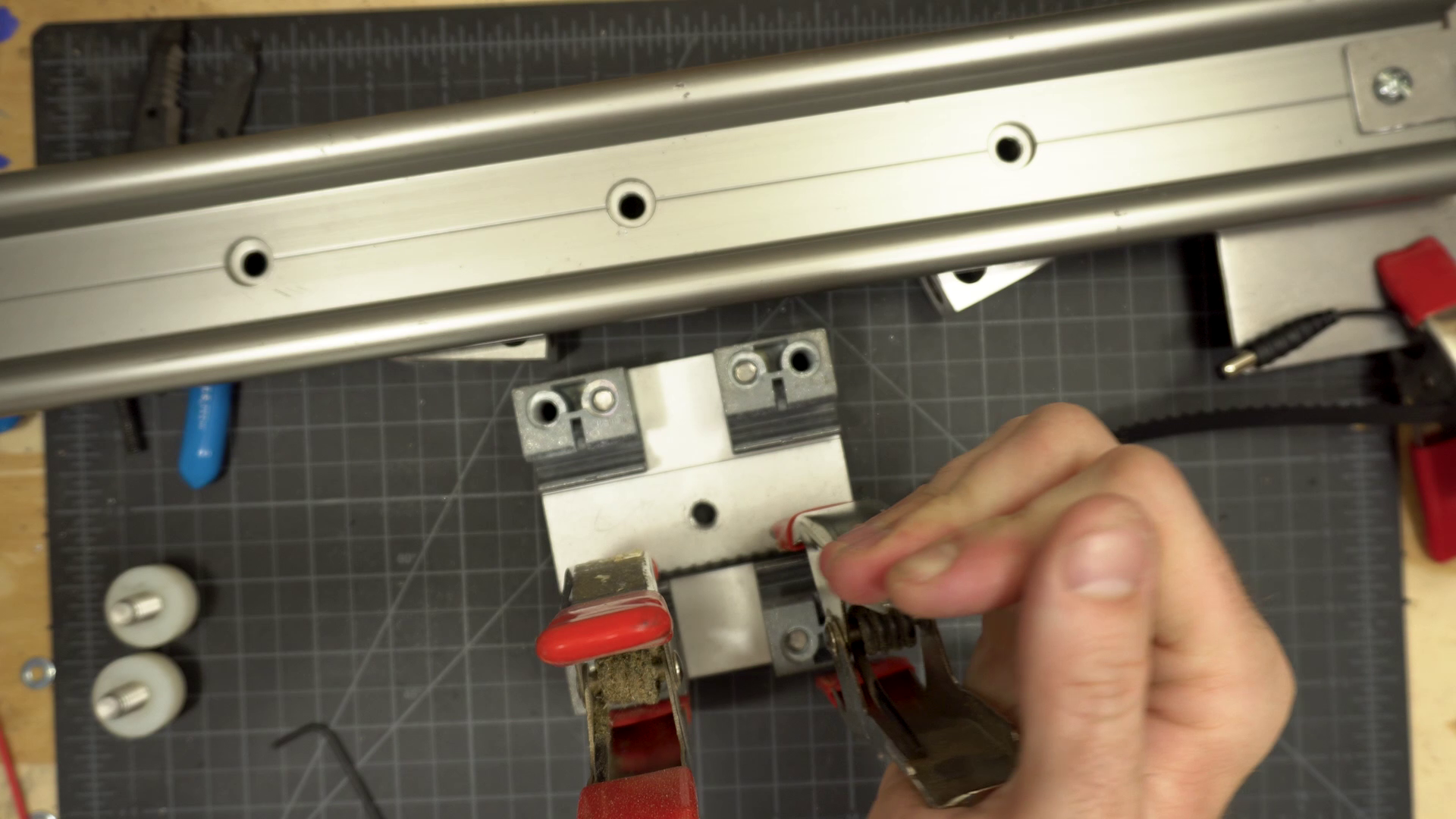
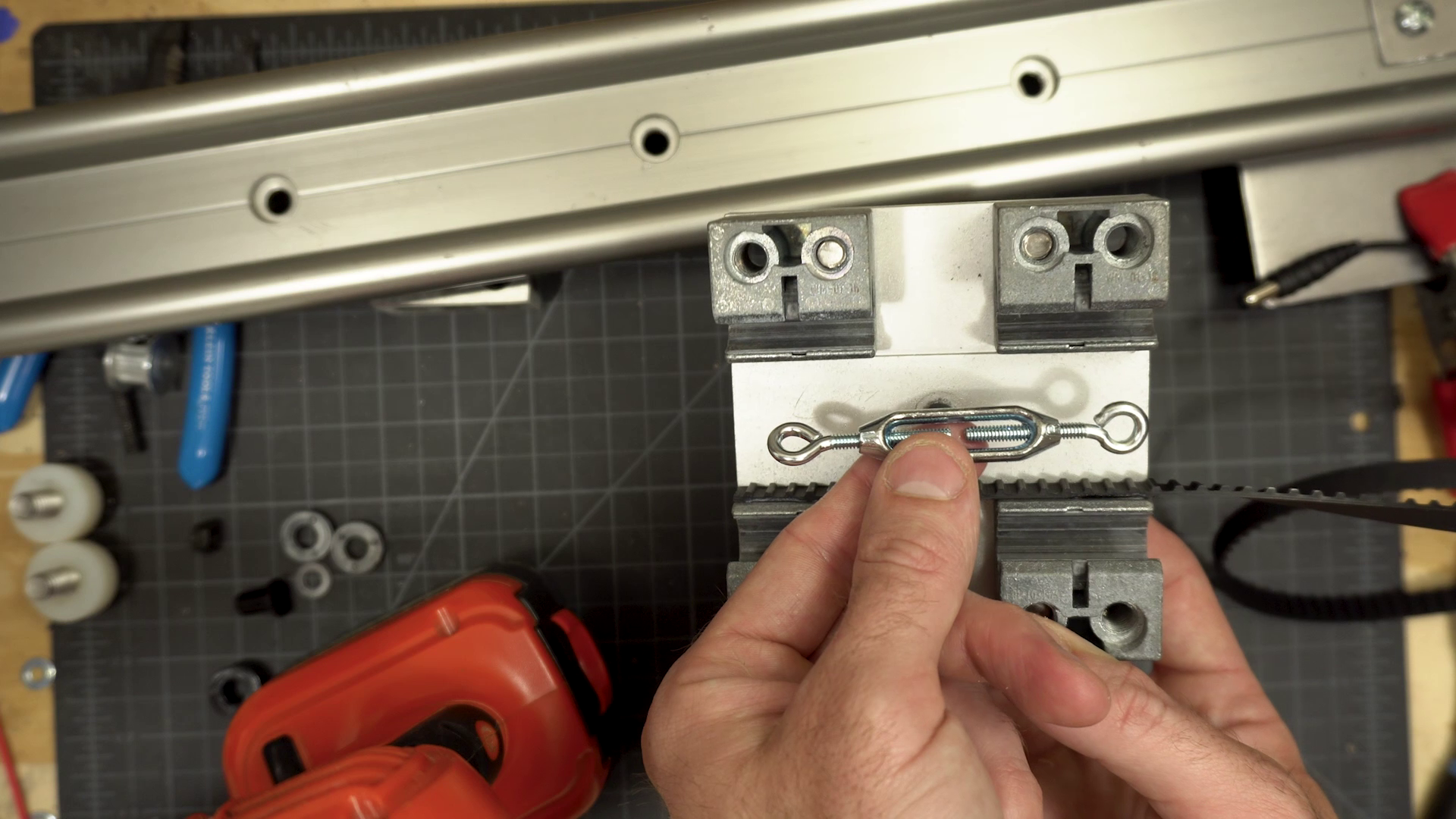
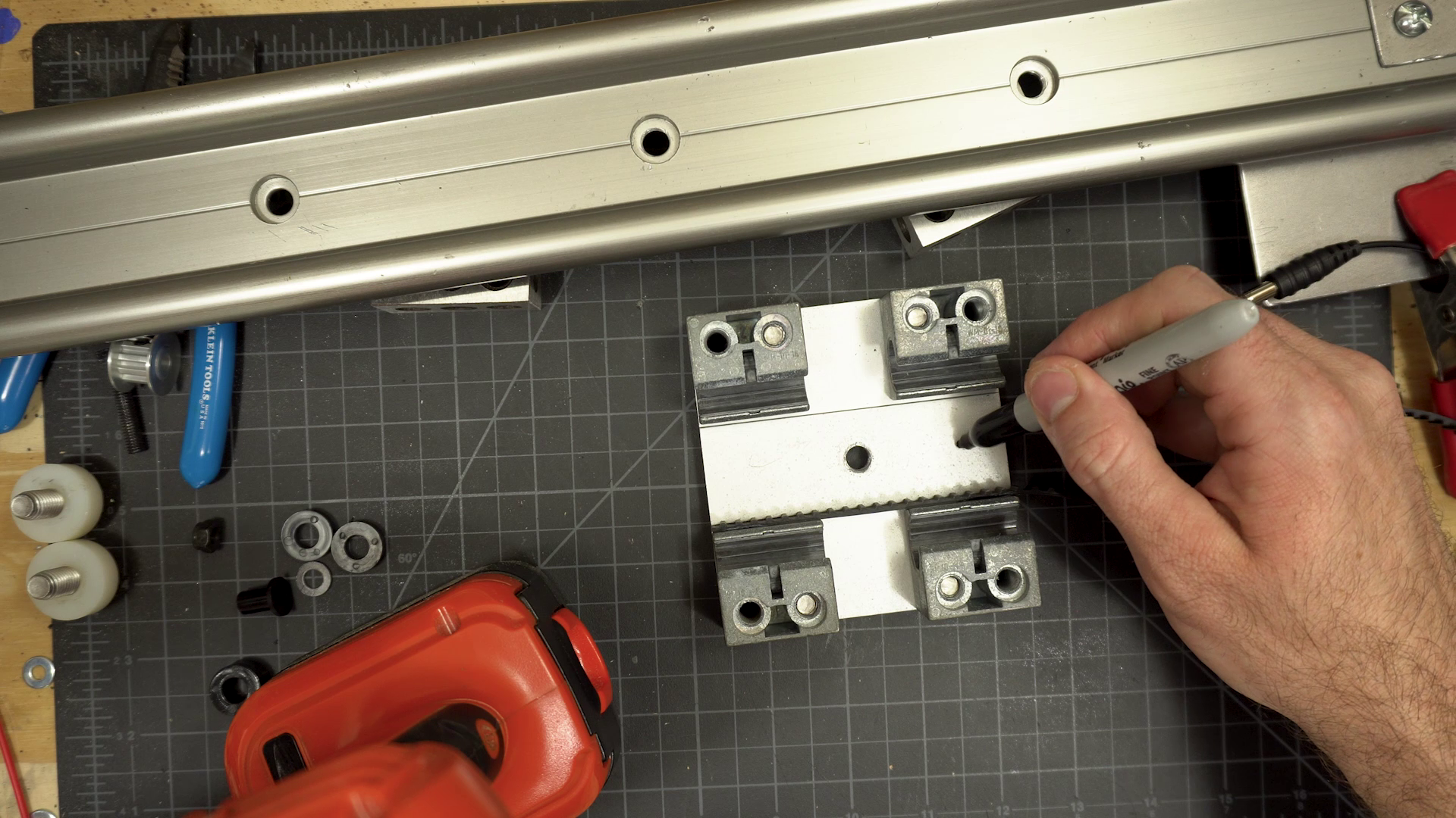
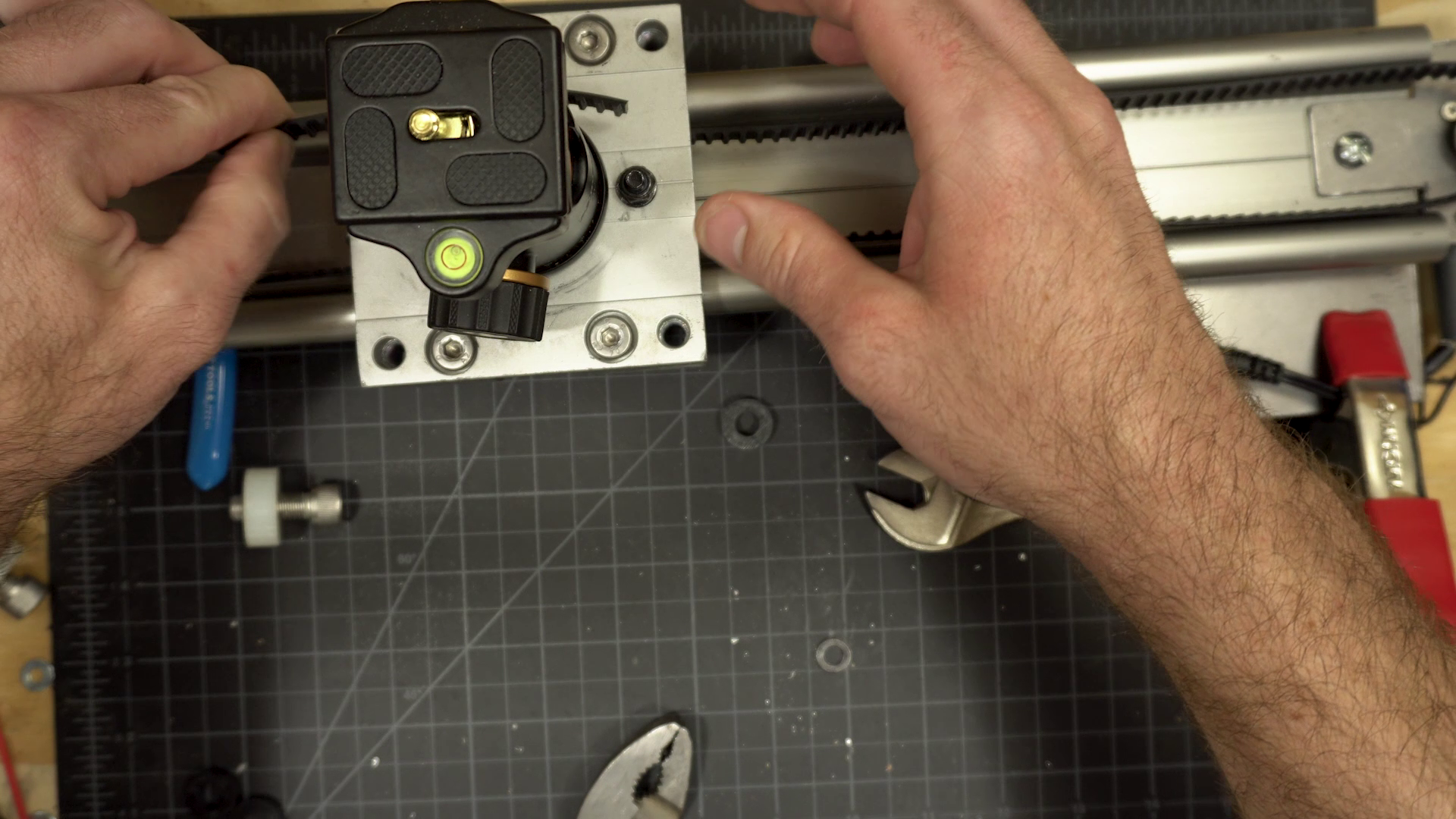
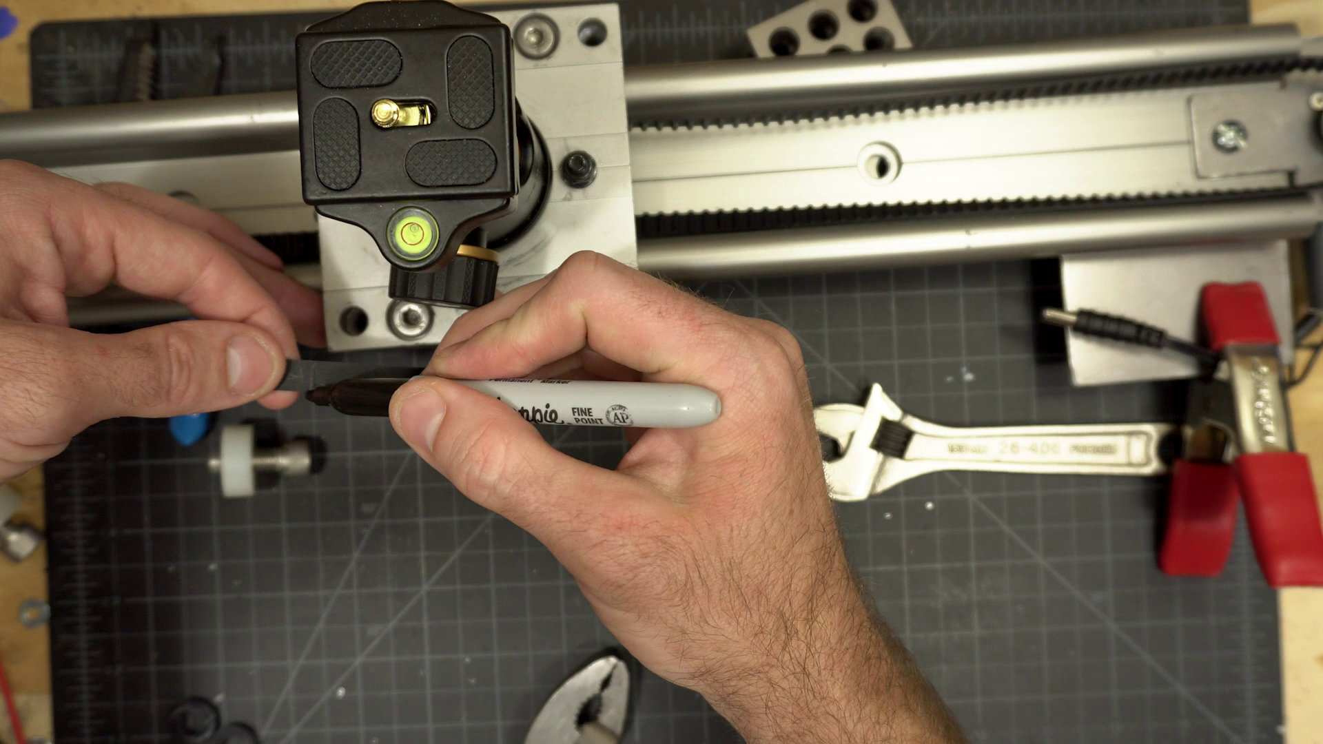
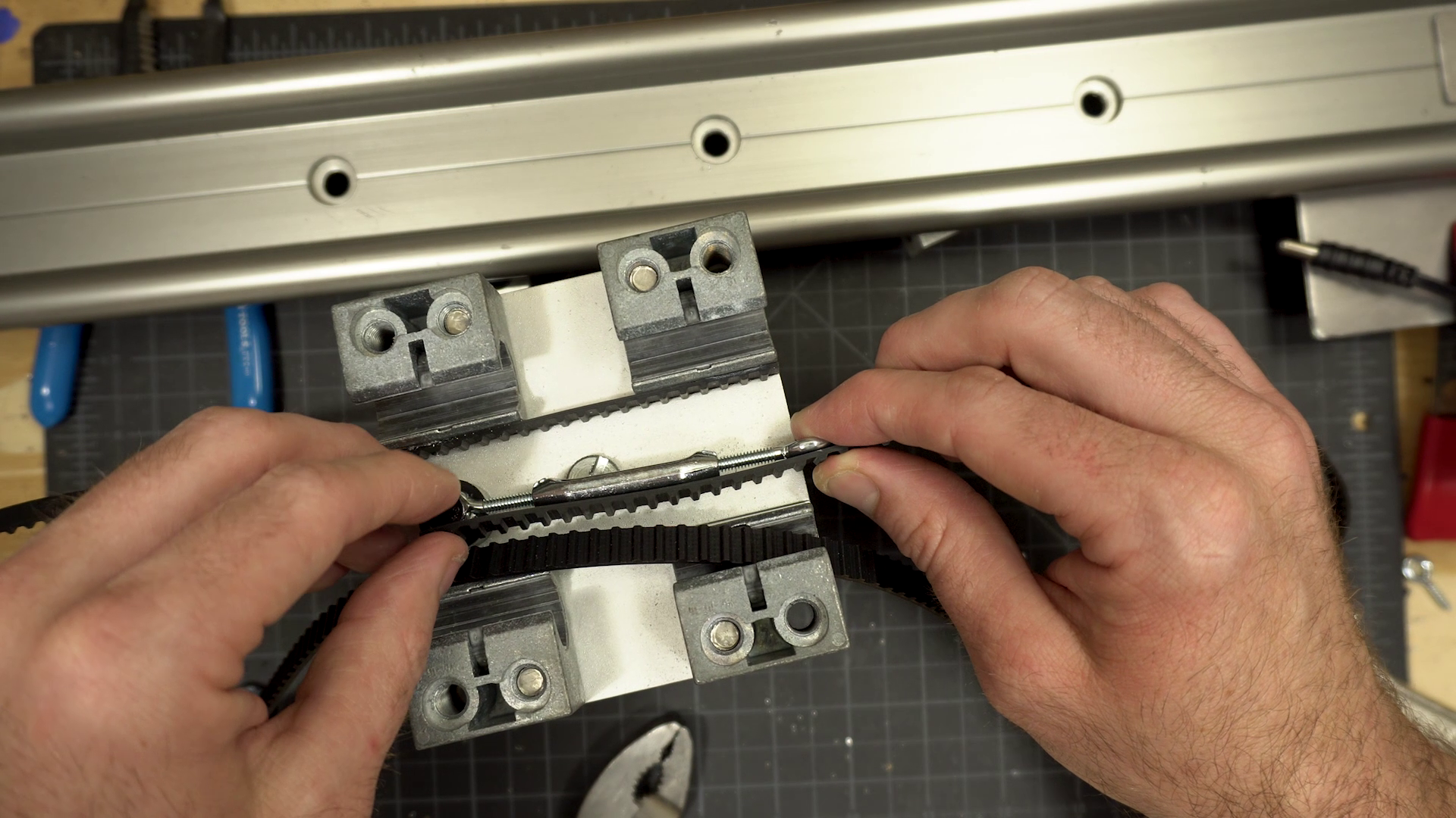
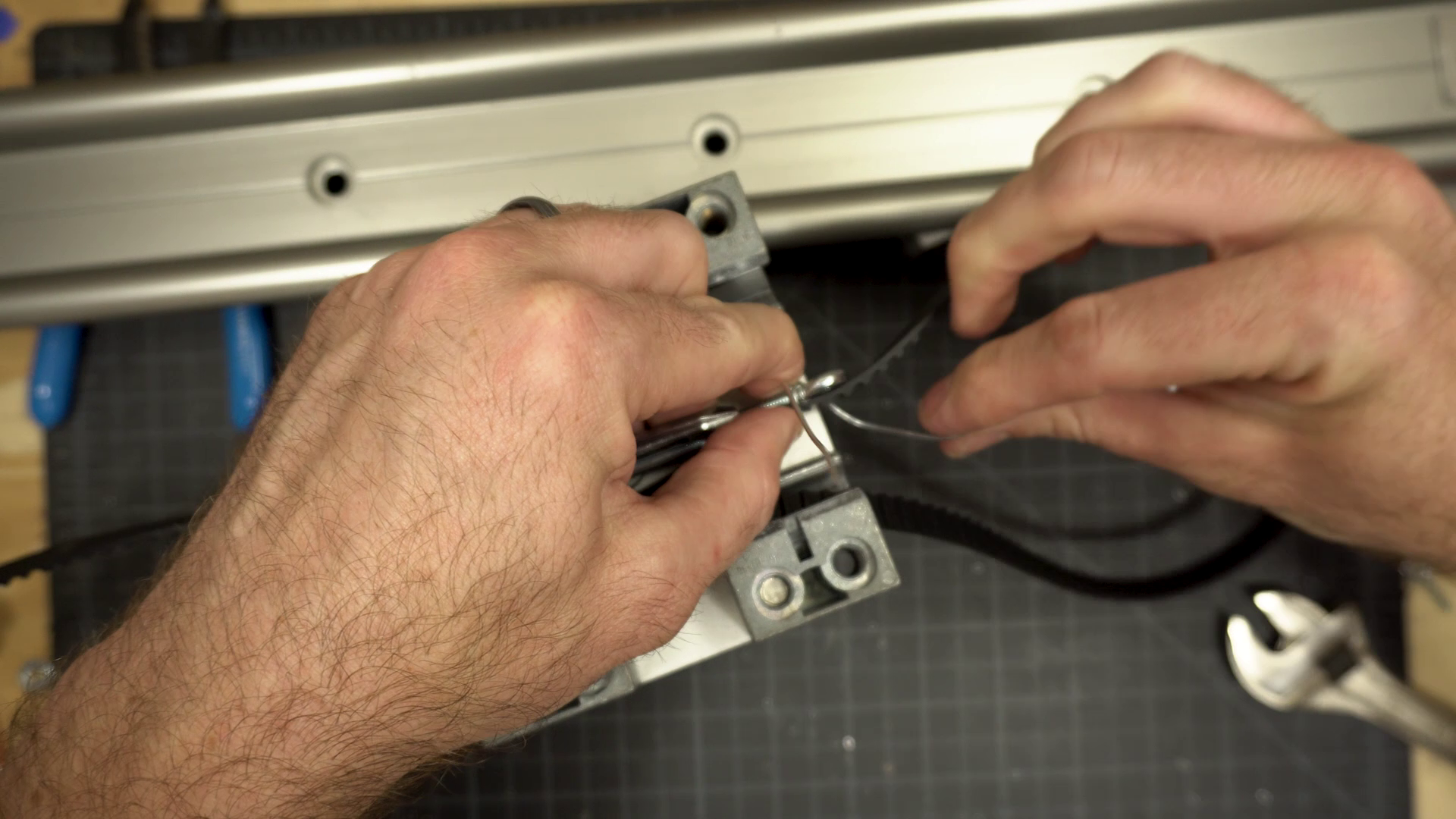
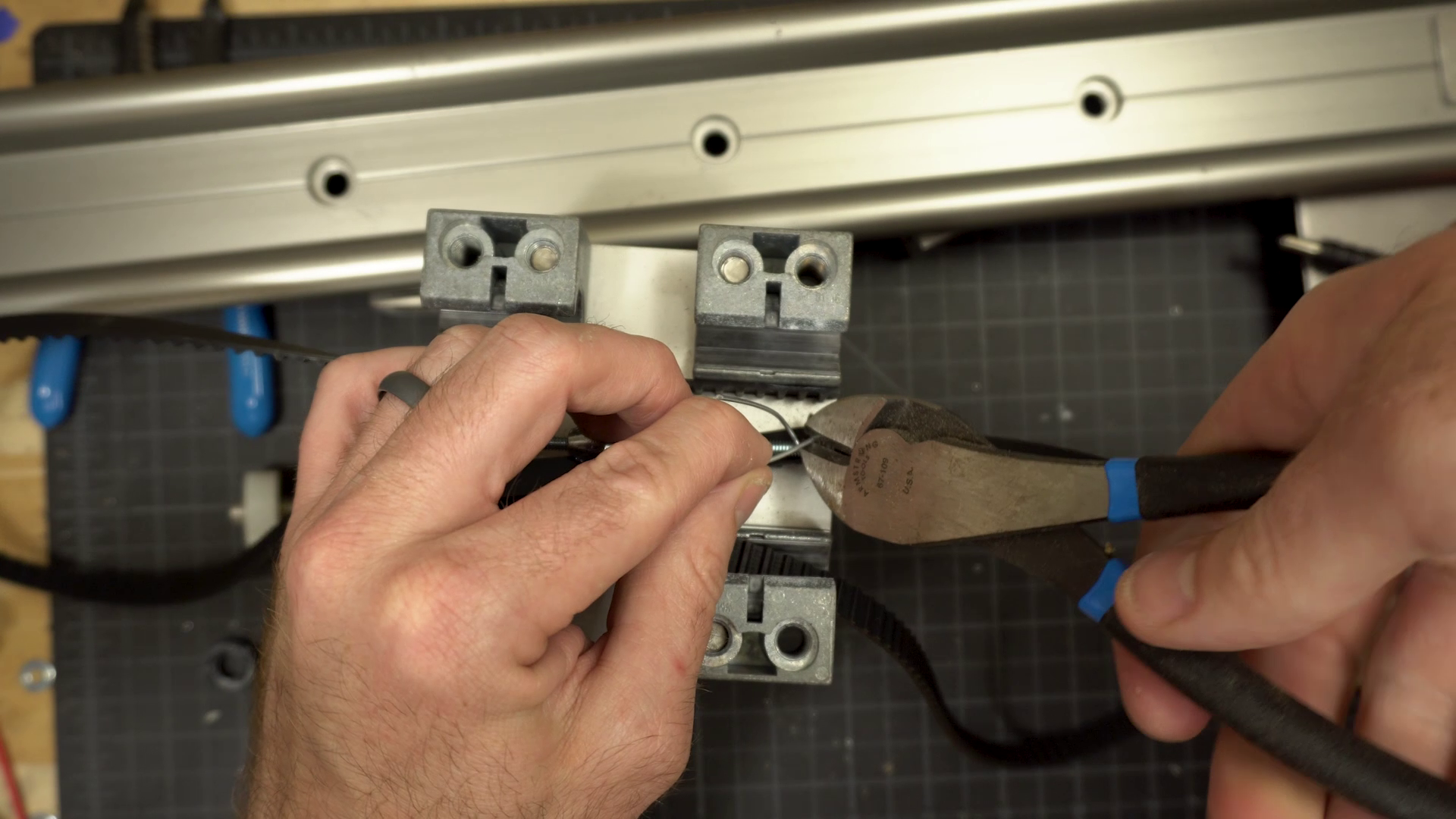
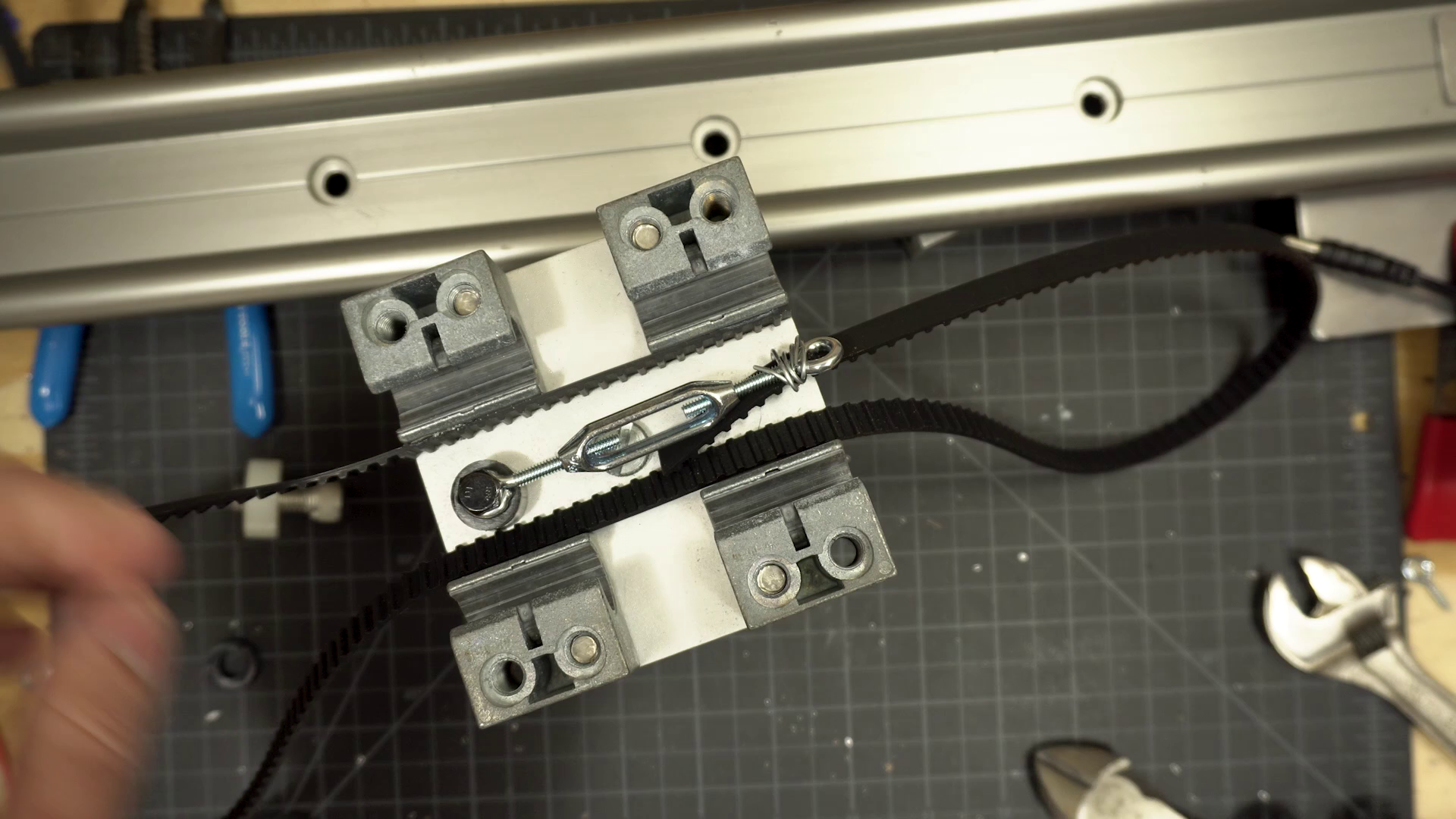
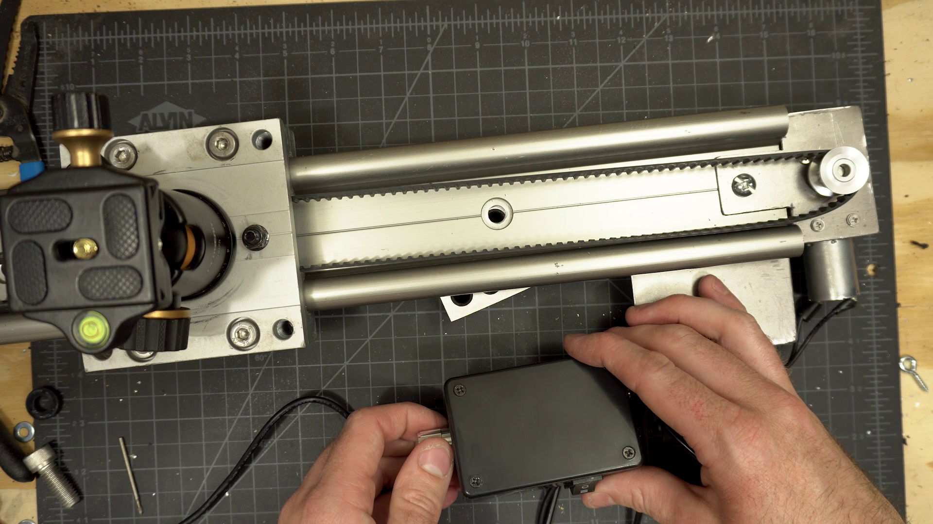
Now grab your sled from the slider, and we want to attach the pulley belt to this so the motor pulls it back and forth. One end we want to permanently attached, so use some super glue and attach the flat side of the belt to the flat side of the rail block under the sled. Then we want to attach the turnbuckle to the sled as well - this will allow us to tighten or loosen the belt as needed. We’ll do this by drilling a ¼” hole off to one side so we don’t interfere with our tripod head, and be sure it’s on the side that the belt is coming out of. Then grab your other bolt, and and a nylon spacer, and thread the bolt up through one eyeloop in the turnbuckle, then the nylon spacer, and then the sled, and then use a nylock nut or lock washer with a nut to attach it. Now attached your tripod head, and you can even attach it before you do anything with the turnbuckle. Then slide the sled back onto the slider, and attach the pulley, wind the belt around both pulleys, and measure out approximately where you need to attach it to the turnbuckle. Make a mark, and then take the pulley back out and the sled back off the slider. Then use some wire and attach the belt to the turnbuckle, I went around multiple times and tightened it frequently with some pliers to make sure it was really secure. Cut the excess wire and pulley belt off. Now it’s back onto the slider with the sled, attach the pulley, wind the belt around both pulleys, tighten using the turnbuckle if needed, and then grab your battery and your motor control box, and we’re ready to go. Then attach everything and double check that it works - make sure it goes both directions, and that the knob gives it a variable speed. I scratched a couple arrows on my box so I would know what what cord goes where. Once you’re all set, stick some velcro onto the battery box platform, and the bottom of the battery box, so it can sit securely while in use.


Then get your slider, attach a camera, and enjoy a beverage of your choice while you film a timelapse with your brand new DIY motorized timelapse slider.
A couple notes about this slider:
My two foot slider and the 1rpm motor takes about 7 minutes to go across at the fastest speed, and takes just over an hour to travel the length at the slowest speed, I’d recommend you time yours out so you have an idea of how long you can film for.
It is strong enough to pull my Sony A7sii with a cinema lens up an incline, and you could probably do vertical moves if you wanted.
You might want to position your motor control box a little further out, I realized pretty quickly that the placement on mine interferes with a few inches of movement.
Be sure the battery you get has an on/off switch - I recommend the one below - initially I was just using one of these external phone charger ones, but if they don’t have a constant 5v draw they’ll turn off.
At a slow speed this rig will still allow for longer shutter speeds if you want that motion blur.
For added motion control consider picking up a small egg timer and using that for some additional panning or tilting.
So you should have your very own DIY motorized timelapse slider - I would absolutely love to see what you create with this so please share that stuff with us if you’d like. If you want to watch the video version of this post, click here, and if you want to see my timelapse reel you can find that here. For more content like this, and things like gear reviews, tips, tricks, tutorials, fun behind-the-scenes posts, and cute dog pics, then sign up for our newsletter, subscribe to Droi Media on YouTube, like us on Facebook, and follow us on Twitter and Instagram.
MATERIALS:
Igus slider: https://amzn.to/2IBXm2y
Sheet metal: https://amzn.to/2LqFzcy
1RPM DC motor: https://amzn.to/2KM3xOi
5V battery: https://amzn.to/2ILldJr
Tripod head: https://amzn.to/2s6MyP6
Female pigtail cables: https://amzn.to/2KM23U6
USB to 5.5mm DC cable: https://amzn.to/2s6wj4m
Small plastic box: https://amzn.to/2GLbhgW
DC motor speed controller: https://amzn.to/2KMQXOI
Pinion pulley (x2): https://goo.gl/vNQx7d
Pulley belt (x4'): https://goo.gl/ZtBZtn
1/4" x 1.5" bolt w/nut (x3)
1/4" nylon bearing
1/4" nylon spacer / washer
M3 bolts (x4)
Turnbuckle (a small one)
Gear note 1: make sure the motor shaft and the bore on the pulleys is the same (6mm ones are above, but 5mm is common too). And be sure the pulley belt and the pulleys will fit as well.
Gear note 2: You could adapt these plans to fit your own slider if you currently have one, you might just have to drill a few additional holes.
Final considerations:
Something I like to have when filming timelapses is a built-in intervalometer option - additional equipment like a timer remote or external intervalometers cost money, add weight to your timelapse rig, and of course they almost all mean more dangling cables to deal with (a big pet peeve of mine). Finding a camera with an internal intervalometer is something you’ll want to consider when looking at your next timelapse project (whether purchasing or renting). Our pals over at Magnanimous Rentals (disclaimer: we rent gear from them) have some great information and options on cameras with built-in timelapse functions. Be sure to check their blog post and video out and next time you need to rent some equipment for a project be sure to visit their website - they’ve got a great selection and really good prices, even for the smaller outfits like ours.
Note: Some of the links above are affiliate links, and purchasing items from these links allows me to continue creating content like this - and the best part is that there is no additional cost to you! Thank you!